@花月 具体一些,需要哪部分?因为本身linux系统相当庞大,基础的操作文档网络上的资料可能更系统一些。如果针对某些特定模块可以提出来。
G
Posts
-
RE: 能不能整理个完整版的说明文档呀posted in Construction
-
RE: 买的lcd屏幕 hdmi的在orangepi里有显示。但是在你们这个板子上黑屏posted in Ubuntu
@tscmga 在你自己做的这个板子上面把HPD信号的驱动能力增强试试。极限情况下可以直接接5V.
下面这款我们有测试过:
https://item.taobao.com/item.htm?spm=2013.1.w4004-23984179834.16.614775a021CPsL&id=654936181802 -
RE: 买的lcd屏幕 hdmi的在orangepi里有显示。但是在你们这个板子上黑屏posted in Ubuntu
@tscmga 这种非标设备暂时没有很好的办法兼容,会导致故此失比,我们之前有测试一款7寸的HDMI+USB触摸的是可以正常使用的,晚一点发链接给你。
-
RE: 请问coolpi 4b 电源输入功率多大合适,有电流保护吗?posted in Peripheral
@night 机器TYPEC前端电源芯片耐压可以达到28V,极限可以到34V,所以你的适配器规格没有任何问题。
开发板的电源部分一直是我们设计最优先考虑的方向,所以前端第一级电源花了很多功夫,考虑到用户各种各样适配器的规格,最终选择目前国内少数几家真正能做车规级别电源方案的厂家。尽量保证前端电源稳定可靠。

-
RE: Coolpi 4b Ubuntu22.04 原生系统posted in Ubuntu
@zensation If this is the case, it means that the image you are using is incorrect, or it is not successfully created.
-
RE: Heatsync optionsposted in Peripheral
@zensation The radiator can be matched with raspberry pi. A separate fan is OK. Normally, it is not necessary to add aluminum alloy fins on the CPU.
-
RE: Coolpi 4b Ubuntu22.04 原生系统posted in Ubuntu
@zensation You can use the shell to log in, expand the partition capacity, and then try to log in from the UI interface.
-
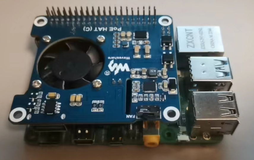
RE: Form Factor and Rasperry PoE HAT compatibilityposted in Peripheral
@Wario
https://buyertrade.taobao.com/trade/detail/tradeSnap.htm?spm=a1z09.2.0.0.3ce72e8d76YGWb&tradeID=2860426011740331265&snapShot=trueThe POE module in the link has been validated and tested and can be directly supported.
-
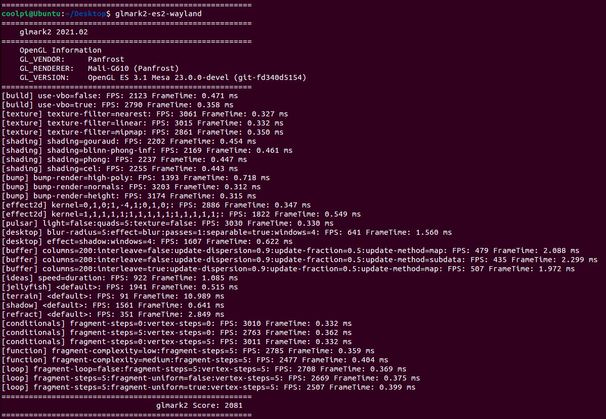
Coolpi 4b with Ubuntu22 running panfrost gpu driver performance testingposted in Ubuntu
CPU
测试方法:
sudo apt install sysbench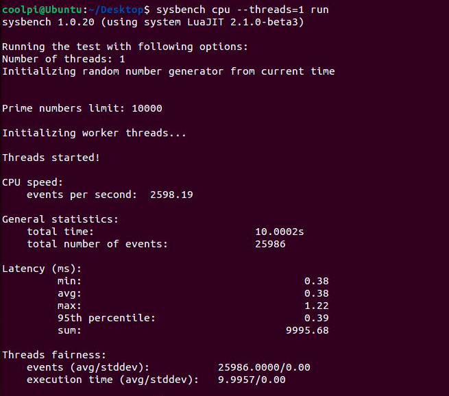
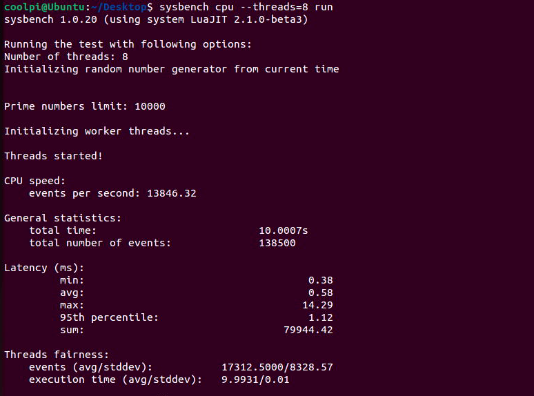
RK3588S单核心每秒事件数2598,8核每秒事件数13846;同步对比 i7-7700 ,单核每秒事件数1438,8核每秒事件数8469。可见ARM在CPU方面并不比X86弱。GPU
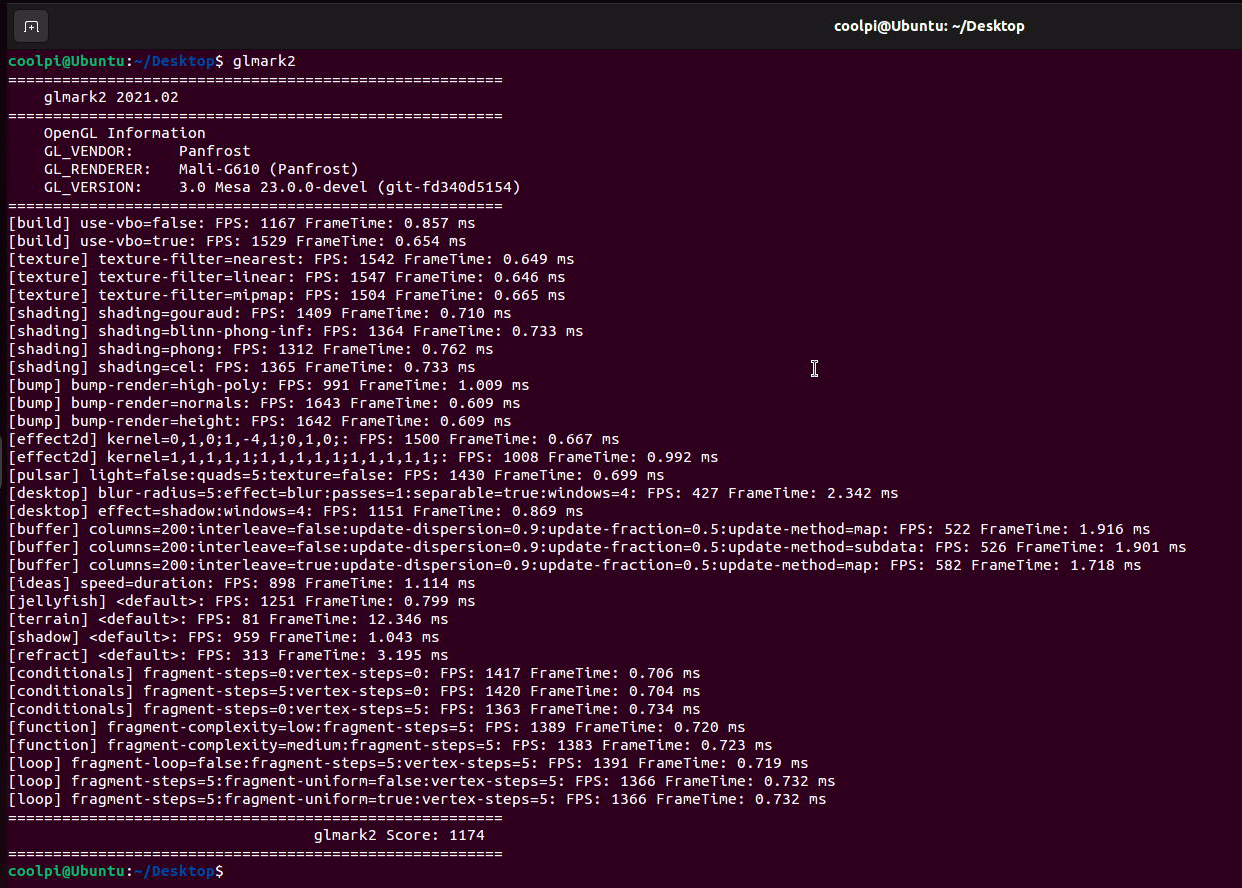
测试方法:
sudo apt-get install glmark2* -yX11 gl
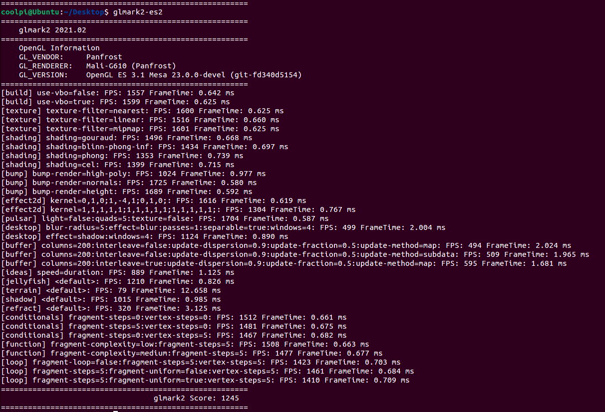
X11 gles 3.1
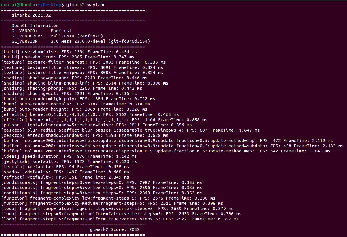
WAYLAND gl
WAYLAND gles 3.1
-
CoolPi-4B硬件扩展五:PWMposted in Hardware
如下表所示,40pin连接器包含7个可用于输出PWM信号的GPIO,其中PIN5 PIN12共用PWM3,PIN38 PIN40共用PWM15,这两个PWM信号同一时刻只能从一个GPIO输出,不能2个GPIO同时输出,所以40PIN连接器一共有5个独立的PWM口可以同时工作 :
序号 端口定义 描述 IO电平 设备节点 5 GPIO0_D4 PWM3_IR_M0 TTL 3.3V /sys/class/pwm/pwmchip3 7 GPIO1_B7 PWM13_M2 TTL 3.3V /sys/class/pwm/pwmchip13 12 GPIO1_A7 PWM3_IR_M3 TTL 3.3V /sys/class/pwm/pwmchip3 32 GPIO3_B1 PWM2_M1 TTL 3.3V /sys/class/pwm/pwmchip2 36 GPIO4_B2 PWM14_M1 TTL 3.3V /sys/class/pwm/pwmchip14 38 GPIO4_B3 PWM15_IR_M1 TTL 3.3V /sys/class/pwm/pwmchip15 40 GPIO3_C3 PWM15_IR_M0 TTL 3.3V /sys/class/pwm/pwmchip15 DTS配置
PWM2口配置如下,其它接口类似,首先配置PWM接口对应的pinctrl,比如PWM2为PWM2_M1,然后使能节点即可。
&pwm2 {
	pinctrl-0 = <&pwm2m1_pins>;
	status = "okay";
};
操作PWM
- 使用 echo 命令将要操作的 PWM 编号 export,注意操作需要root权限。
root@coolpi-4b:/# echo 0 >/sys/class/pwm/pwmchip2/export /*export 之后就会生成/sys/class/pwm/pwmchip2/pwm0目录*/ root@coolpi-4b:/sys/class/pwm/pwmchip2/pwm0# ls capture duty_cycle enable output_type period polarity power uevent- 使用 echo 命令设置 PWM 的周期:
echo 1000000 > /sys/class/pwm/pwmchip2/pwm0/period /*设置PWM一个周期的时间,单位为ns,即一个周期为1KHZ。*/- 使用 echo 命令设置 PWM 的占空比:
echo 500000 > /sys/class/pwm/pwmchip2/pwm0/duty_cycle /*设置PWM一个周期中“ON”的时间,单位为ns,即占空比=duty_cycle/period=50%。*/- 使用 echo 命令使能 PWM
echo 1 > /sys/class/pwm/pwmchip2/pwm0/enable -
RE: CoolPi-4B硬件资料持续更新posted in Hardware
@xuweii 支持wifi6频点,但是达不到WIFI6的性能。COOLPI有一个USB3.0可以当作PCIE使用,可以用作扩展WIFI6或者SSD等外设。当然硬件上要做一些修改,如果有动手能力可以尝试。
-
CoolPi 4B硬件扩展四:GPIOposted in Hardware
40PIN连接器除了debug串口和I2C6,其它都可以用作通用IO。所有的GPIO都支持中断、上下拉和驱动强度配置。
GPIO列表
PIN序号 GPIO编号 节点编号 默认状态 IO电平 3 GPIO0_D5 29 UP TTL 3.3V 5 GPIO0_D4 28 UP TTL 3.3V 7 GPIO1_B7 47 UP TTL 3.3V 11 GPIO4_A0 128 DOWN TTL 3.3V 13 GPIO4_A1 129 DOWN TTL 3.3V 15 GPIO4_A2 130 DOWN TTL 3.3V 19 GPIO1_B2 42 DOWN TTL 3.3V 21 GPIO1_B1 41 DOWN TTL 3.3V 23 GPIO1_B3 43 DOWN TTL 3.3V 29 GPIO4_A3 131 DOWN TTL 3.3V 31 GPIO4_A4 132 DOWN TTL 3.3V 33 GPIO4_A5 133 DOWN TTL 3.3V 35 GPIO4_A6 134 DOWN TTL 3.3V 37 GPIO4_A7 135 DOWN TTL 3.3V 12 GPIO1_A7 39 UP TTL 3.3V 16 GPIO1_A1 33 DOWN TTL 3.3V 18 GPIO1_A0 30 DOWN TTL 3.3V 22 GPIO1_B0 40 UP TTL 3.3V 24 GPIO1_B4 44 UP TTL 3.3V 26 GPIO1_B5 45 UP TTL 3.3V 32 GPIO3_B1 105 UP TTL 3.3V 36 GPIO4_B2 106 UP TTL 3.3V 38 GPIO4_B3 107 UP TTL 3.3V 40 GPIO3_C3 115 UP TTL 3.3V 测试命令
向内核申请GPIO,写入对应的GPIO值直接申请,比如申请控制GPIO4A0,则使用命令:
echo 128 > /sys/class/gpio/export写入后,可以看到已经生成节点:
/sys/class/gpio/gpio128/相应gpio节点下面的接口,比如GPIO4A0:
root@ubuntu:~# ll /sys/class/gpio/gpio128/
total 0
drwxr-xr-x 3 root root    0 Nov 21 15:23 ./
drwxr-xr-x 3 root root    0 Nov 21 15:23 ../
-rw-r--r-- 1 root root 4096 Nov 21 15:24 active_low
lrwxrwxrwx 1 root root    0 Nov 21 15:24 device -> ../../../gpiochip4/
-rw-r--r-- 1 root root 4096 Nov 21 15:24 direction
-rw-r--r-- 1 root root 4096 Nov 21 15:24 edge
drwxr-xr-x 2 root root    0 Nov 21 15:24 power/
lrwxrwxrwx 1 root root    0 Nov 21 15:24 subsystem -> ../../../../../../class/gpio/
-rw-r--r-- 1 root root 4096 Nov 21 15:23 uevent
-rw-r--r-- 1 root root 4096 Nov 21 15:24 value
设置GPIO4A0为输出口
root@ubuntu:/sys/class/gpio/gpio128# echo out >direction
root@ubuntu:/sys/class/gpio/gpio128# cat direction
out
设置输出高电平
root@ubuntu:/sys/class/gpio/gpio128# cat value
0
root@ubuntu:/sys/class/gpio/gpio128# echo 1 >value
root@ubuntu:/sys/class/gpio/gpio128# cat value
1
实际万用表测试PIN 11输出的电压为3.3V
备注:
-
direction: 参数为“out”(输出)和“in”(输入),可读可写;
-
value: 参数为“0”(低电平)和“1”(高电平),可读可写;
-
edge:可以监听对应引脚的事件,需要把direction设置为输入
参数为”none”(无中断触发), “rising”(上升沿触发), “falling”(下降沿触发), “both”(上升、下降都沿触发),用户层可以使用poll,设置events为POLLPRI | POLLERR等待事件触发,当对应的模式触发后,会返回事件的消息,此时需要读取value值,以表示改触发已经处理,否则会一直poll到原事件; -
active_low:此值可以反转value中的值;
-
-
ubuntu22.04一键安装ROS2环境posted in Ubuntu
root登录shell键入如下命令:
root@ubuntu:/# wget http://fishros.com/install -O fishros && bash fishros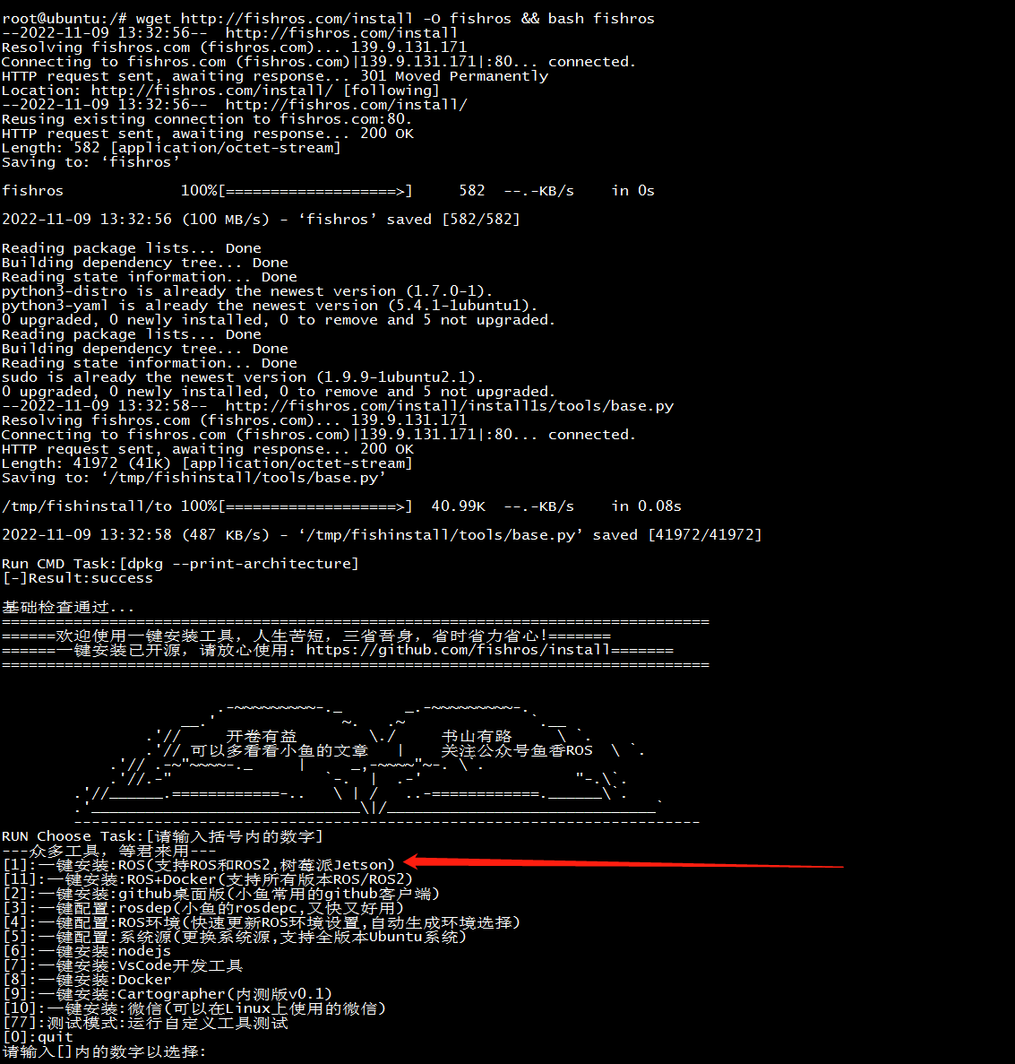
选择更新源速度会大幅度提高
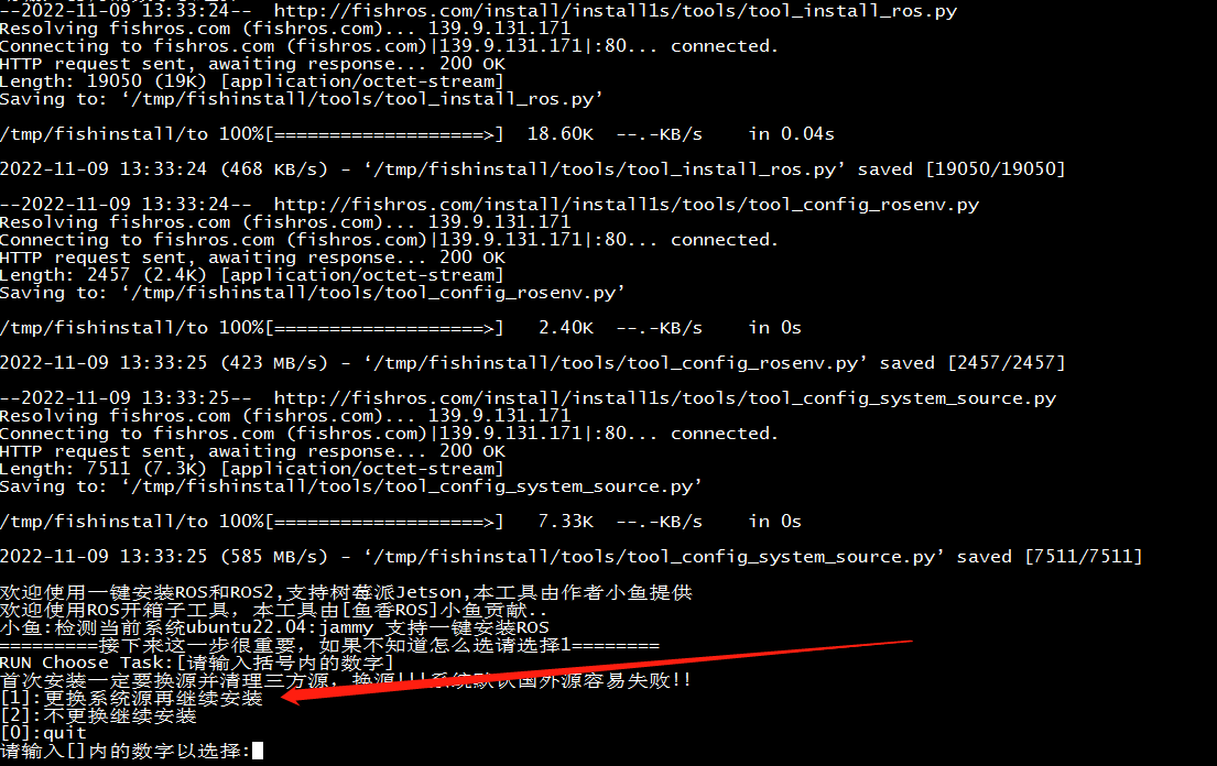
选择humble

选择桌面版

安装成功界面
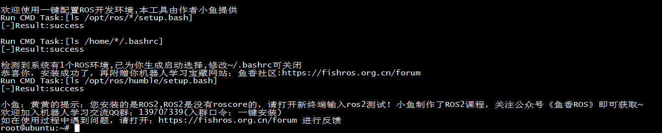
简单测试:
两个shell终端分别输入下面两条指令$ros2 run demo_nodes_py listener $ros2 run demo_nodes_cpp talker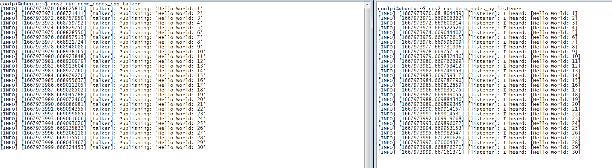
小乌龟测试:
两个shell终端分别输入下面两条指令$ ros2 run turtlesim turtlesim_node $ ros2 run turtlesim turtle_teleop_key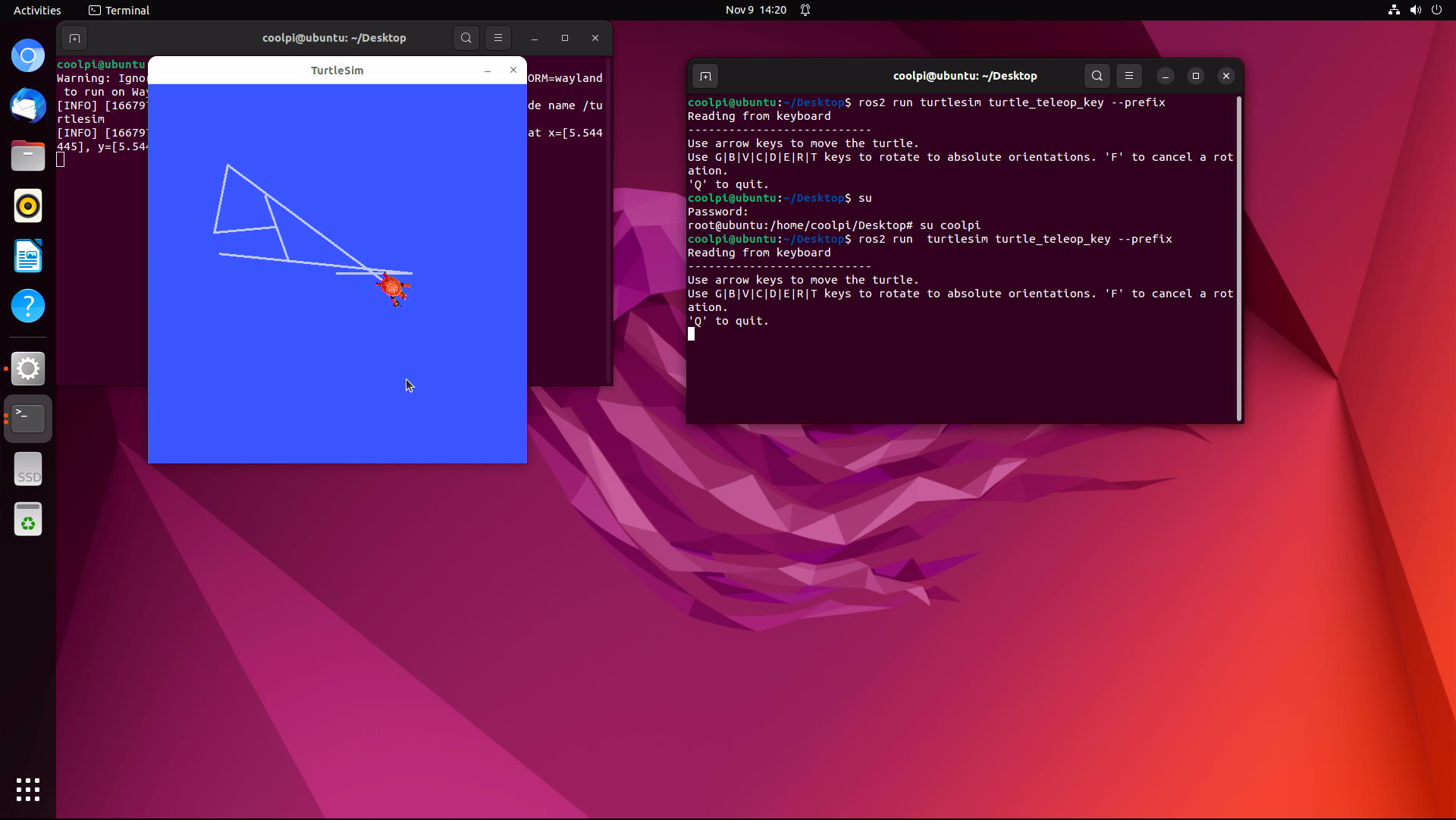
-
CoolPi 4B硬件扩展三:I2Cposted in Hardware
如下表所示,coolpi 4b的40PIN连接器可以引出4组I2C总线出来,其中I2C1 I2C3 I2C5是独立I2C接口,机器内部没有和其它设备复用,I2C6板子内部有接RTC时钟芯片HYM8563,地址为51H,所以外设使用I2C6端口的时候注意地址不要冲突。
I2C位置
序号 端口定义 描述 IO状态 3 I2C1_SDA_M2 I2C1数据 Internal 2.2K Pull up 3.3V 5 I2C1_SCL_M2 I2C1时钟 Internal 2.2K Pull up 3.3V 27 I2C6_SDA_M3 I2C6数据 Internal 2.2K Pull up 3.3V 28 I2C6_SCL_M3 I2C6时钟 Internal 2.2K Pull up 3.3V 31 I2C3_SCL_M2 I2C3时钟 Internal 2.2K Pull up 3.3V 33 I2C3_SDA_M2 I2C3数据 Internal 2.2K Pull up 3.3V 35 I2C5_SCL_M2 I2C5时钟 Internal 2.2K Pull up 3.3V 37 I2C5_SDA_M2 I2C5数据 Internal 2.2K Pull up 3.3V DTS配置
设备驱动的配置方式参考I2C6节点,注意不使用I2C功能确保节点的status为disabled,否则可能会导致其它功能异常。
&i2c1 {
	status = "okay";
	pinctrl-names = "default";
	pinctrl-0 = <&i2c1m2_xfer>;
};

&i2c3 {
	status = "okay";
	pinctrl-names = "default";
	pinctrl-0 = <&i2c3m2_xfer>;
};

&i2c5 {
	status = "okay";
	pinctrl-names = "default";
	pinctrl-0 = <&i2c5m2_xfer>;
};

&i2c6 {
	status = "okay";
	pinctrl-names = "default";
	pinctrl-0 = <&i2c6m3_xfer>;

	hym8563: hym8563@51 {
		compatible = "haoyu,hym8563";
		reg = <0x51>;
		#clock-cells = <0>;
		clock-frequency = <32768>;
		clock-output-names = "hym8563";
		pinctrl-names = "default";
		pinctrl-0 = <&hym8563_int>;
		interrupt-parent = <&gpio0>;
		interrupts = <RK_PB0 IRQ_TYPE_LEVEL_LOW>;
		status = "okay";
	};

};
测试工具及方法
git clone git://git.kernel.org/pub/scm/utils/i2c-tools/i2c-tools.git cd i2c-tools make -j8 sudo make install root@ubuntu:/# i2cdetect -y 6 0 1 2 3 4 5 6 7 8 9 a b c d e f 00: -- -- -- -- -- -- -- -- 10: -- -- -- -- -- -- -- -- -- -- -- -- -- -- -- -- 20: -- -- -- -- -- -- -- -- -- -- -- -- -- -- -- -- 30: -- -- -- -- -- -- -- -- -- -- -- -- -- -- -- -- 40: -- -- -- -- -- -- -- -- -- -- -- -- -- -- -- -- 50: -- UU -- -- -- -- -- -- -- -- -- -- -- -- -- -- 60: -- -- -- -- -- -- -- -- -- -- -- -- -- -- -- -- 70: -- -- -- -- -- -- -- -- I2C6节点上可以扫描到地址为51H的设备,即HYM8563。工具也支持其他读写操作。可以自行研究。 -
CoolPi 4B硬件扩展二:Serial portposted in Hardware
串口位置
下表罗列了40PIN连接器可以用做UART功能的引脚,目前除了debug串口以外还可以扩展5路独立串口。最大波特率1.5M。IO电平是TTL 3.3V。注意:串口号和实际系统的节点不是一一对应,实际操作需要按照表格对应的设备节点。
序号 端口定义 描述 IO电平 设备节点 29 UART0_TX_M2 UART0 发送 TTL 3.3V /dev/ttyS6 31 UART0_RX_M2 UART0 接收 TTL 3.3V /dev/ttyS6 33 UART3_TX_M2 UART3 发送 TTL 3.3V /dev/ttyS3 35 UART3_RX_M2 UART3 接收 TTL 3.3V /dev/ttyS3 19 UART4_RX_M2 UART4 接收 TTL 3.3V /dev/ttyS4 23 UART4_TX_M2 UART4 发送 TTL 3.3V /dev/ttyS4 16 UART6_TX_M1 UART6 发送 TTL 3.3V /dev/ttyS2 18 UART6_RX_M1 UART6 接收 TTL 3.3V /dev/ttyS2 24 UART7_RX_M2 UART7 接收 TTL 3.3V /dev/ttyS7 26 UART7_TX_M2 UART7 发送 TTL 3.3V /dev/ttyS7 DTS配置
用户需要使用哪个串口在DTS打开对应节点即可,status = "okay"代表开启,status = "disabled"代表关闭。注意不使用UART功能确保对应节点的status是disabled状态,否则可能会导致其它功能异常。
&uart0 {
	pinctrl-names = "default";
	pinctrl-0 = <&uart0m2_xfer>;
	status = "okay";
};

&uart3 {
	pinctrl-names = "default";
	pinctrl-0 = <&uart3m2_xfer>;
	status = "okay";
};

&uart4 {
	pinctrl-names = "default";
	pinctrl-0 = <&uart4m2_xfer>;
	status = "okay";
};

&uart6 {
	pinctrl-names = "default";
	pinctrl-0 = <&uart6m1_xfer>;
	status = "okay";
};

&uart7 {
	pinctrl-names = "default";
	pinctrl-0 = <&uart7m2_xfer>;
	status = "okay";
};
shell测试命令
功能测试采用回环测试(对应串口的TX RX信号短接)。
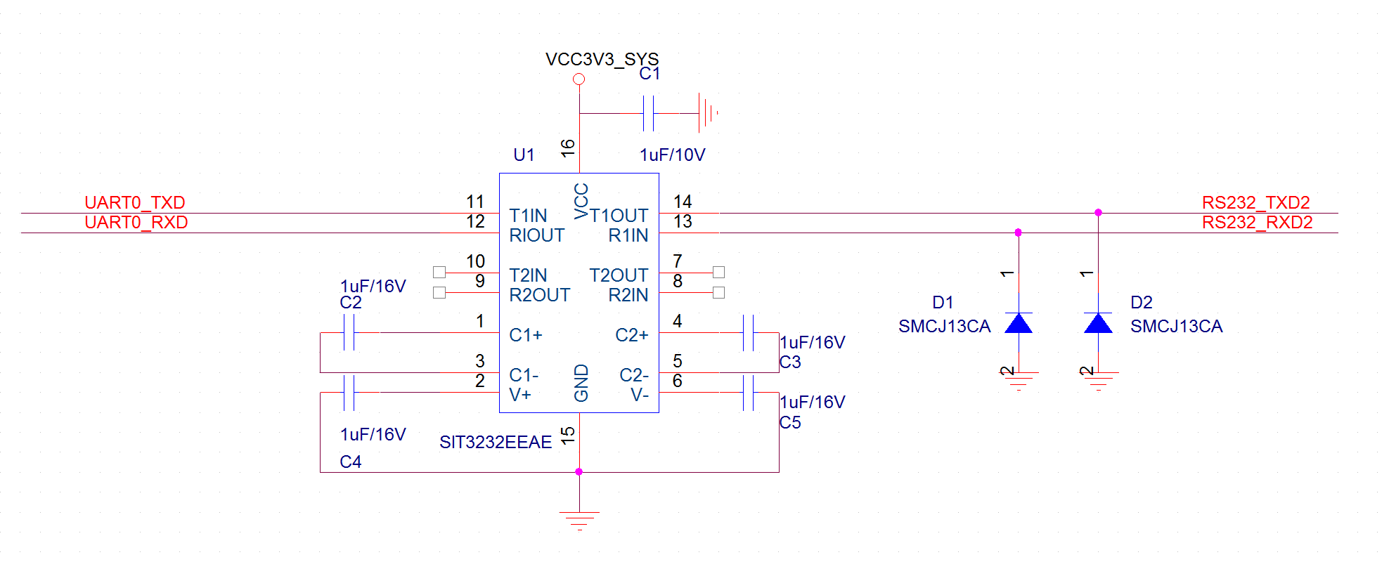
stty -F /dev/ttyS6 raw speed 115200 //配置PIN29 PIN31对应的串口波特率为115200
echo "hello world" > /dev/ttyS6 //发送字符串
cat /dev/ttyS6 //接收字符串
RS232电路
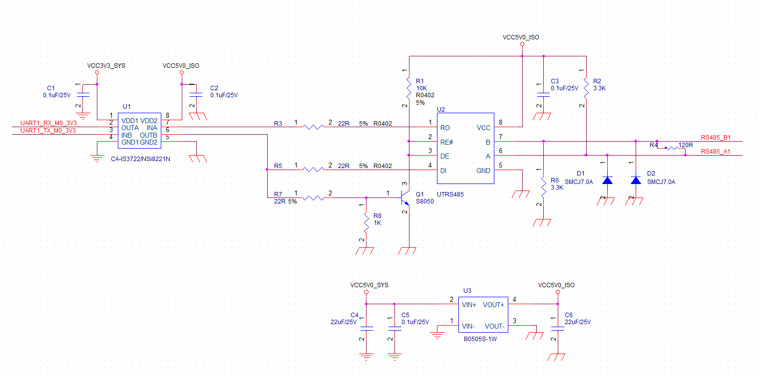
隔离485电路