G
Best posts made by george
-
RE: 请问coolpi 4b 电源输入功率多大合适,有电流保护吗?posted in Peripheral
@night 机器TYPEC前端电源芯片耐压可以达到28V,极限可以到34V,所以你的适配器规格没有任何问题。
开发板的电源部分一直是我们设计最优先考虑的方向,所以前端第一级电源花了很多功夫,考虑到用户各种各样适配器的规格,最终选择目前国内少数几家真正能做车规级别电源方案的厂家。尽量保证前端电源稳定可靠。

-
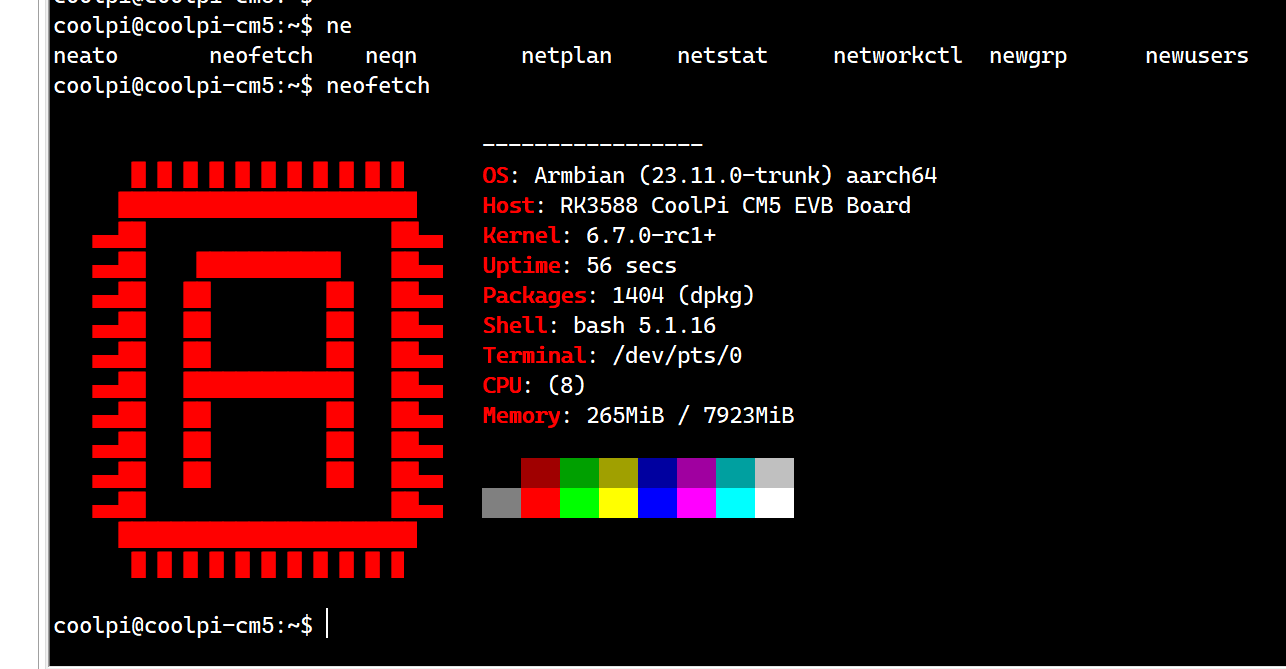
ubuntu22.04一键安装ROS2环境posted in Ubuntu
root登录shell键入如下命令:
root@ubuntu:/# wget http://fishros.com/install -O fishros && bash fishros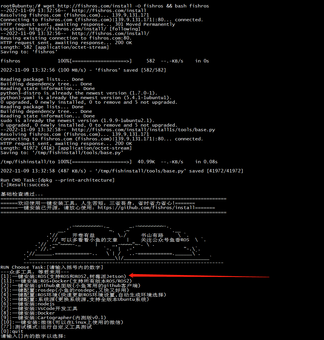
选择更新源速度会大幅度提高
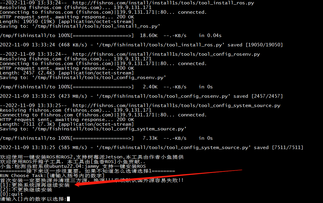
选择humble

选择桌面版

安装成功界面
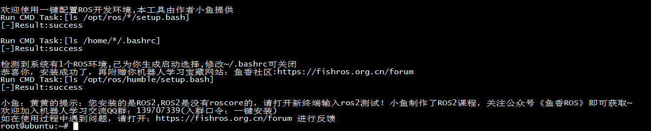
简单测试:
两个shell终端分别输入下面两条指令$ros2 run demo_nodes_py listener $ros2 run demo_nodes_cpp talker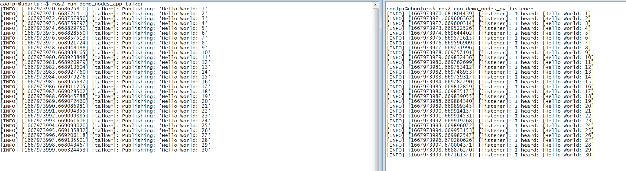
小乌龟测试:
两个shell终端分别输入下面两条指令$ ros2 run turtlesim turtlesim_node $ ros2 run turtlesim turtle_teleop_key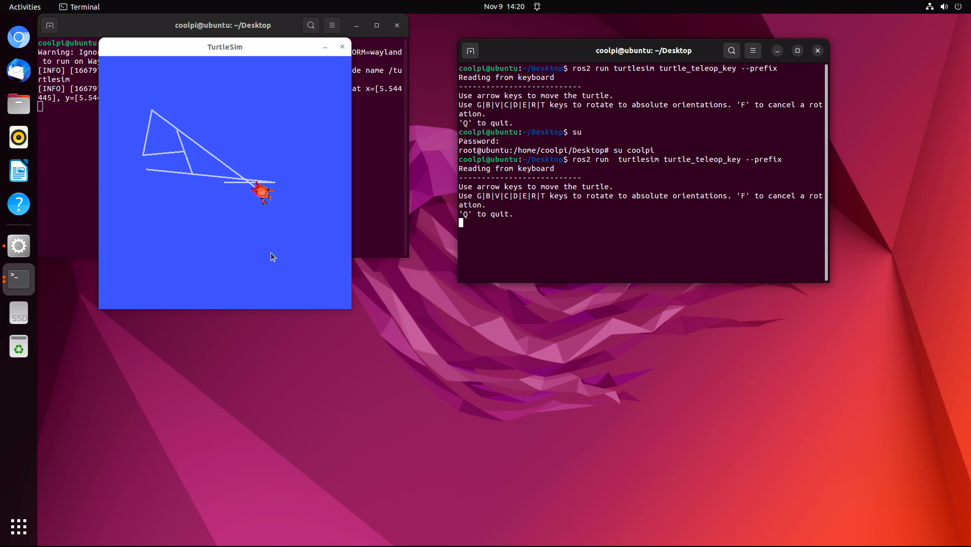
-
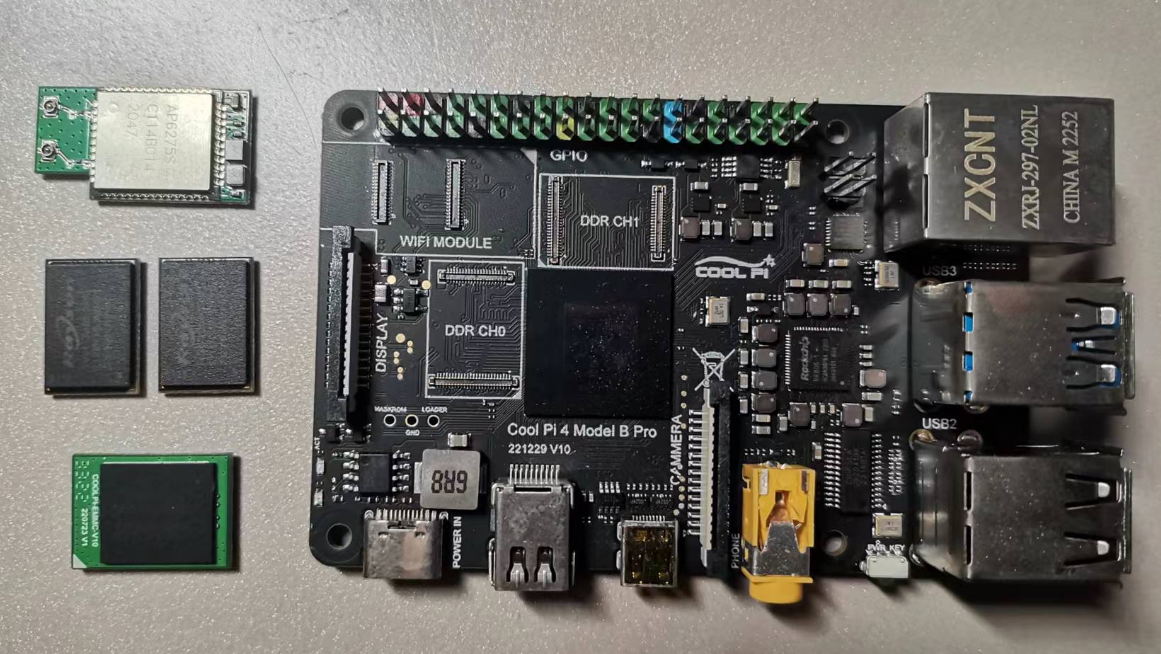
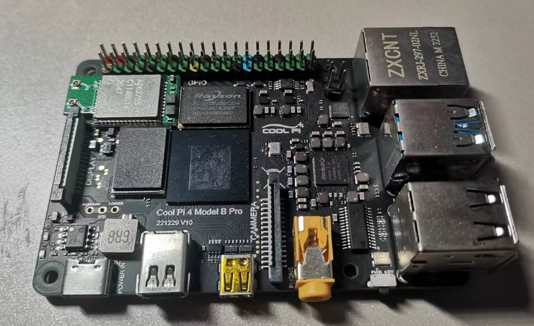
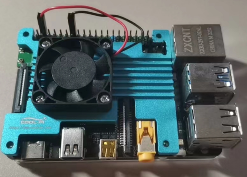
CoolPI 4B-PRO Product Introductionposted in News
-
Picture first
-
4G-32G Memory Capacity Replacement.
-
The WIFI module is replaceable and supports models such as 2.4G 5G WIFI6.
-
EMMC module supports up to 256G.
-
-
RE: 自定义bootloaderposted in Pi 4B
@zehui
启动的流程是一样的,目前uboot的结构如下:FIT description: FIT Image with ATF/OP-TEE/U-Boot/MCU Created: Wed Feb 28 09:32:41 2024 Image 0 (uboot) Description: U-Boot Created: Wed Feb 28 09:32:41 2024 Type: Standalone Program Compression: uncompressed Data Size: 1389728 Bytes = 1357.16 KiB = 1.33 MiB Architecture: AArch64 Load Address: 0x00200000 Entry Point: unavailable Hash algo: sha256 Hash value: e8eeabe5b2891390396b4cb77a33c5bb8da03b1da33a64274a077cf386f2b5aa Image 1 (atf-1) Description: ARM Trusted Firmware Created: Wed Feb 28 09:32:41 2024 Type: Firmware Compression: uncompressed Data Size: 200008 Bytes = 195.32 KiB = 0.19 MiB Architecture: AArch64 Load Address: 0x00040000 Hash algo: sha256 Hash value: c902200be1343fe569e54778c286005b1c6163606664c463a24d787be4376966 Image 2 (atf-2) Description: ARM Trusted Firmware Created: Wed Feb 28 09:32:41 2024 Type: Firmware Compression: uncompressed Data Size: 24576 Bytes = 24.00 KiB = 0.02 MiB Architecture: AArch64 Load Address: 0xff100000 Hash algo: sha256 Hash value: 225d6bf0712f850648223365ba06a73ba5f6315fb8a9580f23ab48ece795f91e Image 3 (atf-3) Description: ARM Trusted Firmware Created: Wed Feb 28 09:32:41 2024 Type: Firmware Compression: uncompressed Data Size: 24576 Bytes = 24.00 KiB = 0.02 MiB Architecture: AArch64 Load Address: 0x000f0000 Hash algo: sha256 Hash value: aa71013e72d7ab4be264c1093b155ef06e65d0a263d552be25b13c8ddf285586 Image 4 (optee) Description: OP-TEE Created: Wed Feb 28 09:32:41 2024 Type: Firmware Compression: uncompressed Data Size: 465304 Bytes = 454.40 KiB = 0.44 MiB Architecture: AArch64 Load Address: 0x08400000 Hash algo: sha256 Hash value: 66e30bf9e879405a49797aaa6c08ca1c41aa325443e910af42e3df309e65909b Image 5 (kern-fdt) Description: cp4/uboot.dtb Created: Wed Feb 28 09:32:41 2024 Type: Flat Device Tree Compression: uncompressed Data Size: 141854 Bytes = 138.53 KiB = 0.14 MiB Architecture: AArch64 Hash algo: sha256 Hash value: ba43bc47ab29f0cbcba25658712ac3d3c6349a30486c76d5b720310e58f02de3 Image 6 (fdt) Description: U-Boot dtb Created: Wed Feb 28 09:32:41 2024 Type: Flat Device Tree Compression: uncompressed Data Size: 7065 Bytes = 6.90 KiB = 0.01 MiB Architecture: AArch64 Hash algo: sha256 Hash value: 987a71d492c0045c4964bbed7799da0eee5276a2b60b5a1335fc2d37fdfcf944 Default Configuration: 'conf' Configuration 0 (conf) Description: rk3588s-cp4 Kernel: unavailable Firmware: atf-1 FDT: fdt kern-fdt Loadables: uboot atf-2 atf-3 optee -
We have been making progress!!posted in PI CM5 Laptop
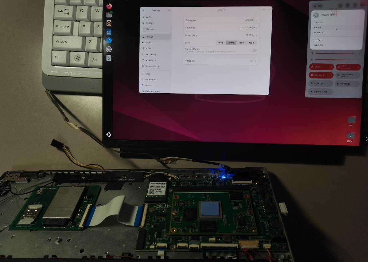
5G
4K (3840*2160) LCD
One more thing, everyone guess
-
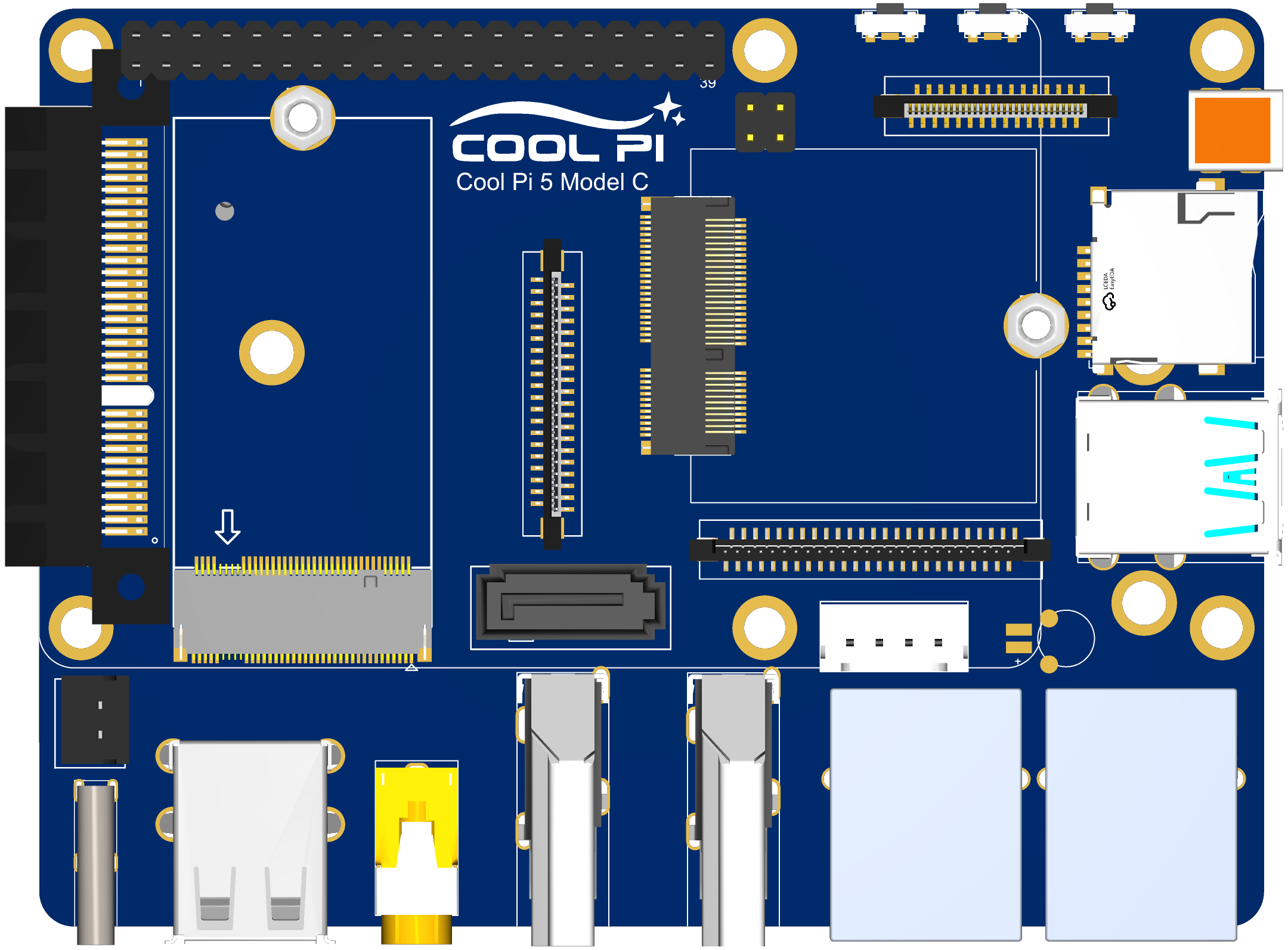
Introduction to COOL PI CM5 interfaceposted in Pi CM5
Top-level interface
-
The 2X20 pin interface is compatible with CP4 and integrates multiple UART, I2C, SPI, CAN and other functions.
-
Three function keys are PWR, RST and LOADER.
-
2X2 PIN POE connector,such as CP4.
-
30pin fpc vertical connector can directly drive standard 30PIN EDP interface LCD. Resolution up to 3840 * 2160
-
The MICRO HDMI-RX interface can support up to 4KP60 video signal input.
-
TF card with self-locking.
-
Two native USB3.0 interfaces, one of which supports OTG function.
-
Two Gigabit Ethernet interfaces, one of which supports POE function.
-
Two HDMI2.1 interfaces with a maximum resolution of 8K.
-
Stereo headphone stand with MIC input function.
-
Two native USB2.0 interfaces.
-
One TYPEC power supply interface, consistent with CP4.
-
The external power interface of 2PIN can support DC power input.
-
1 standard PCIE 4X connector, currently only supports PCIE3.0 2X/1X mode.
-
SSD interface, only PCIE-M2-2242 size hard disk is supported.
-
Standard 7PIN SATA3.0 interface, 4PIN power interface.
-
M.2 WIFI module interface, supporting multiple general WIFI modules.
-
Dual MIPI LCD interfaces support simultaneous output of two MIPI interface LCDs. The resolution of a single LCD is up to 1920 * 1200. It supports the MIPI DSC function.
-
Four independent MIPI camera interfaces support four camera inputs at the same time. It can be configured as 2X4LINE or 4X2LINE mode.
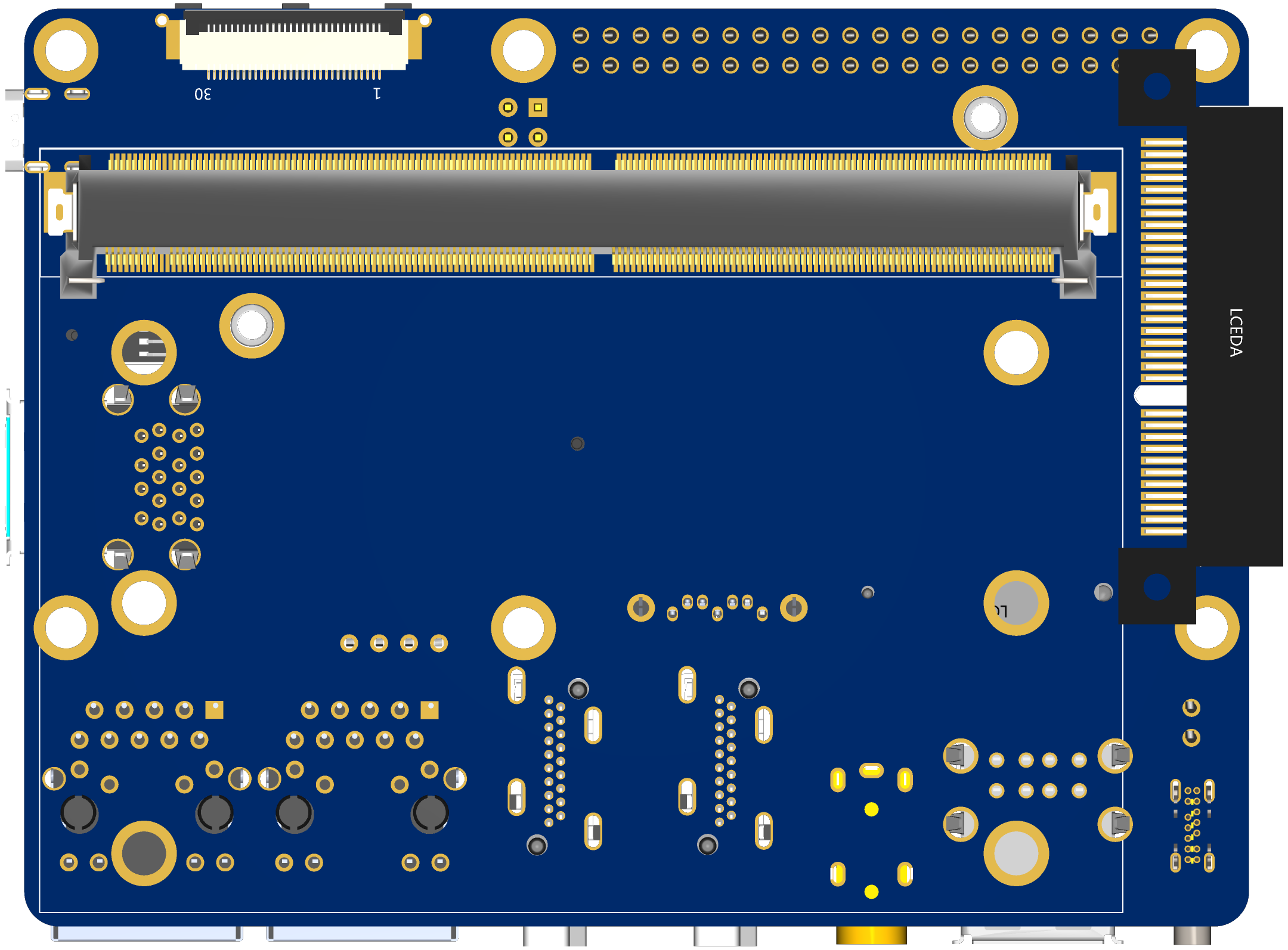
Bot-level interface
-
One 30PIN EDP interface can directly drive LCD output.
-
MXM 314PIN core board connector.
Welcome to put forward good suggestions. We can consider revising them.
-
-
How to upgrade the boot loader of coolpi 4b?posted in Pi 4B
If you need to boot armbian normally, you need to update the loader file to version 0104.
Follow the steps below to update the loader:
-
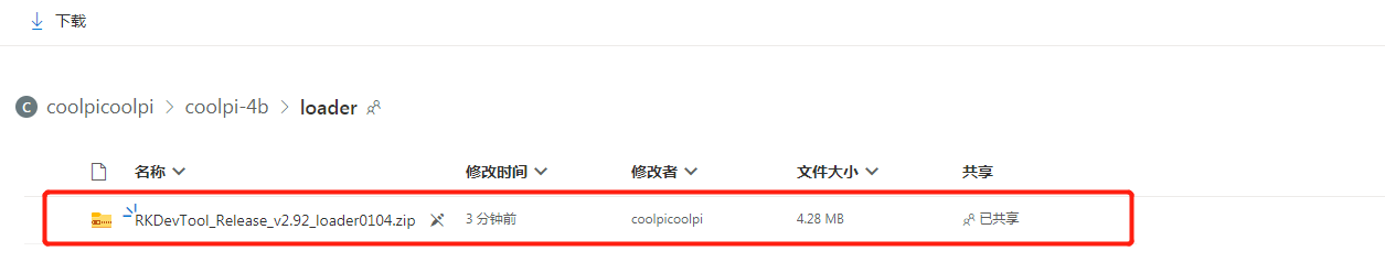
Download the latest loader file One Drive
![5594e1d4-3a7b-46fc-a7b5-2a9fe418dfc0-image.png]
-
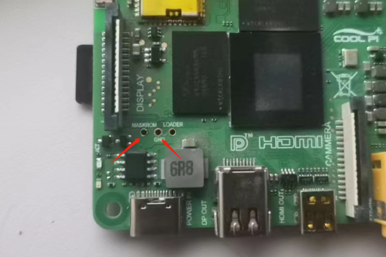
Short the 2 pins shown by the arrow.
-
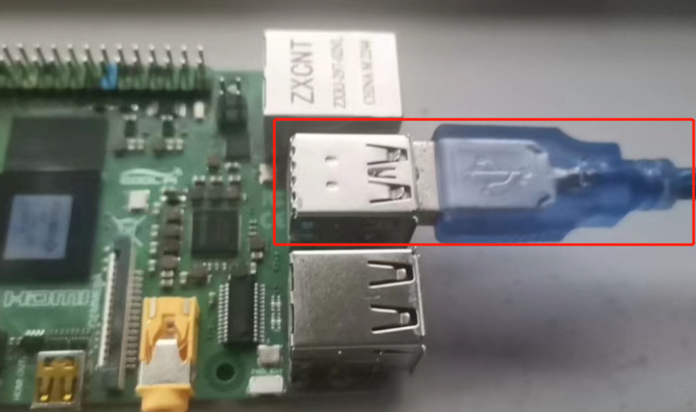
The USB interface and computer connection.
-
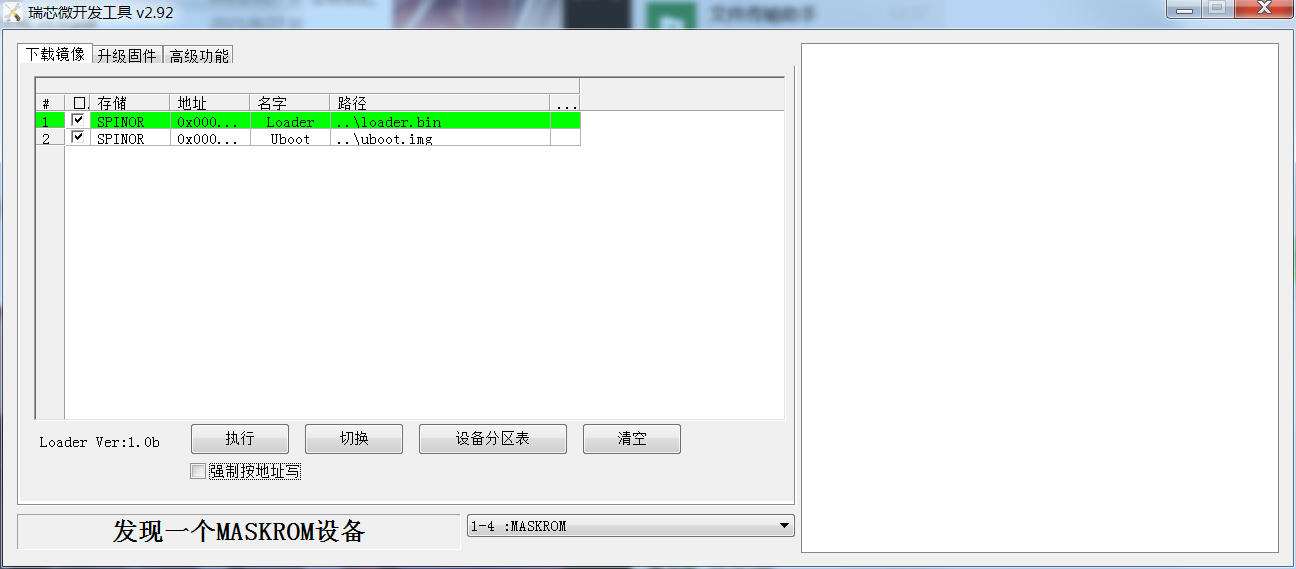
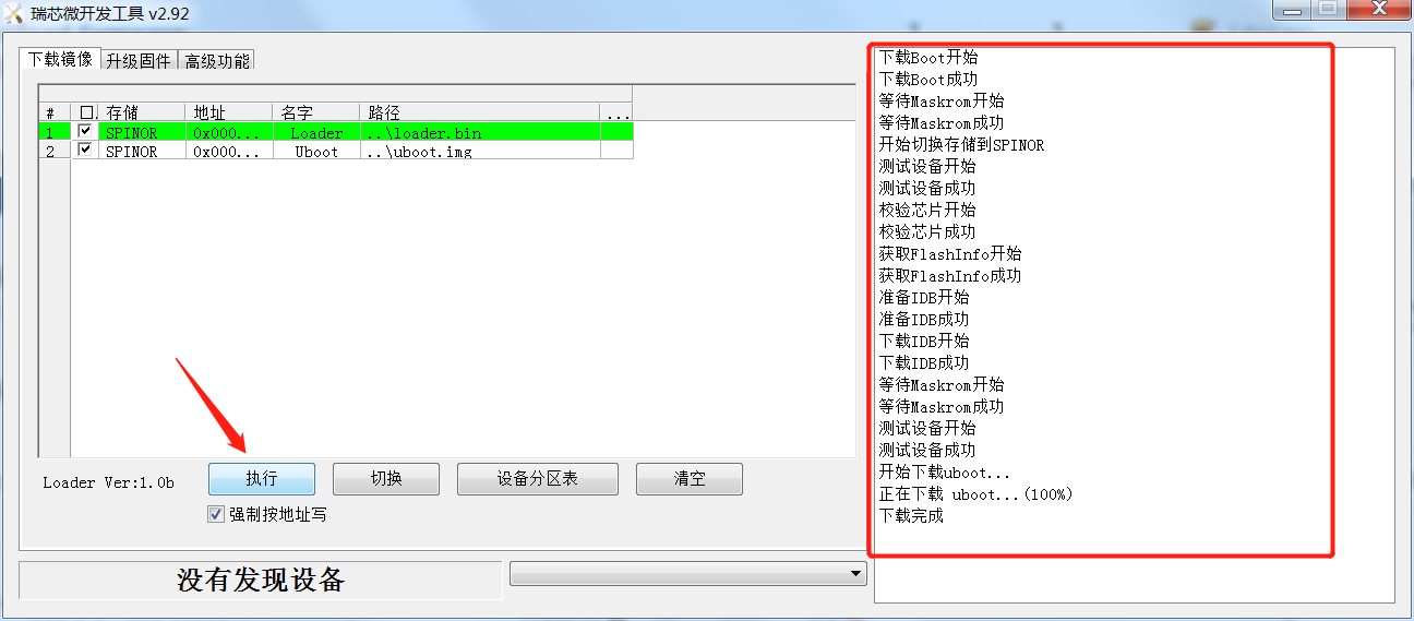
Plug in the power supply and open the upgrade software. The machine enters the maskrom upgrade mode.
-
choose to write by address
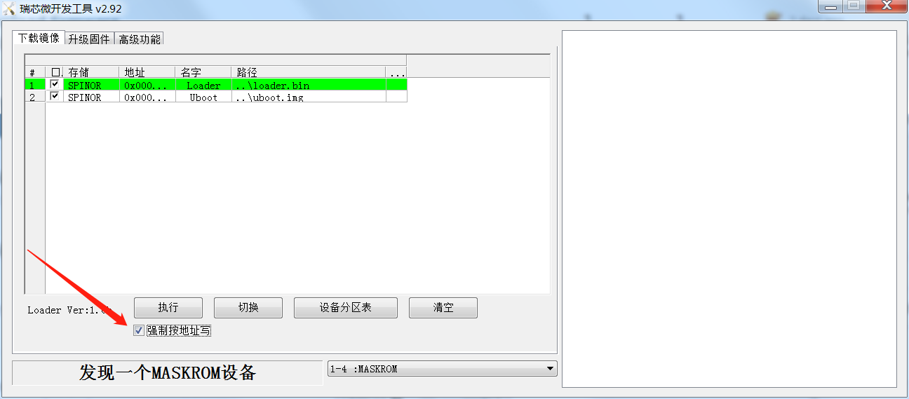
-
Click Execute to complete the loader update.
-
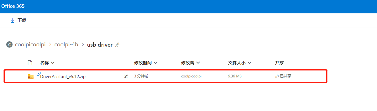
If the computer prompts that the USB driver cannot be found, please download and install the driver software first.One Drive
-
Latest posts made by george
-
RE: Guru, please help me !posted in PI CM5 Laptop
@Rock
Write the image to a USB drive, then boot the system from the USB drive, format EMMC after system startup, and then enter UMS to re burn. -
RE: Cool Pi Cm5-Laptop Linux Quick Start Guideposted in PI CM5 Laptop
git checkout 6.1.75
./build-kernel.sh arm64
The deb file will be generated in the higher-level directory of the code and copied to the machine for installation.
-
RE: Any other distro booting?posted in PI CM5 Laptop
@petersen77
The compilation of Mesa is closely related to the DRM version, so pay attention to the version. -
RE: Cool Pi Cm5-Laptop Linux Quick Start Guideposted in PI CM5 Laptop
@Momo-0
TYPEC is only related to DTS, and the main issue with the sound card is Tinymix configuration. -
RE: Cool Pi Cm5-Laptop Linux Quick Start Guideposted in PI CM5 Laptop
@Momo-0
The official default configuration of ARMBIN's loadaddr and optee conflicts and needs to be modified to 0x200000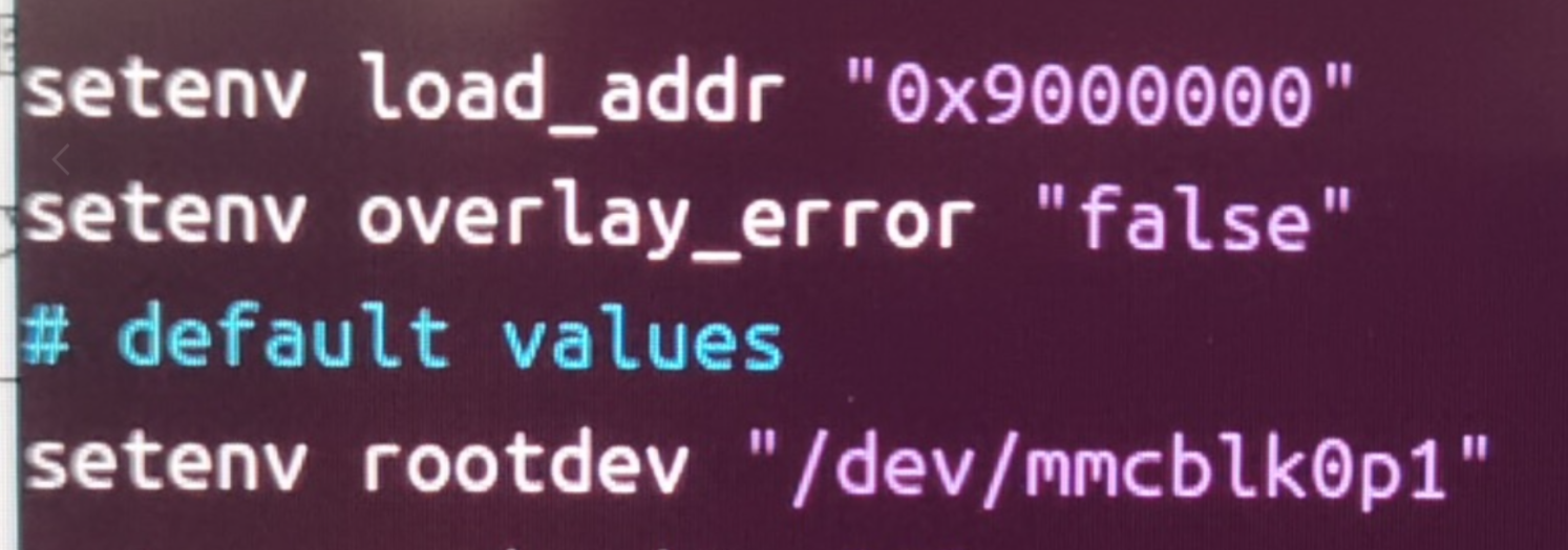
-
RE: Any other distro booting?posted in PI CM5 Laptop
@petersen77
Compile and install mesa24 or higher versions. -
Precautions for MOTION Remote Monitoringposted in Pi Gateway CP1B/CP2B/CP3B/CP3B-P
- Install the motion package
sudo apt install motion -y- Insert USB camera and recognize video node normally
admin@cp2b:~$ ls /dev/ |grep video video0 video1- Modify the following configurations
framerate 60 //Change frame rate to 100 stream_maxrate 60 //Add configuration webcontrol_localhost off //Support remote control stream_localhost off off //Support remote stream- Increase services
sudo systemctl start motion sudo systemctl enable motion sudo reboot- Accessing the camera, please note that HTTPS is not supported
http://you-ip-address:8081
-
RE: Any other distro booting?posted in PI CM5 Laptop
@petersen77
The rc.local script actually only performs simple scaling operations, which can be implemented anywhere in the system, such as creating a service yourself.
Regarding GPU issues, it is necessary to compile and install the latest version of Mesa by oneself. -
Coolpi WIFI Support Listposted in Pi Gateway CP1B/CP2B/CP3B/CP3B-P
Wifi Support List
Model Specifications Manufacturer Interface Supporting Machines RTL8852BE Wi-Fi 6+BT5.2 REALTEK PCIe 2.0 x1、M.2 Key E CM5-AIBOX/CM5-GENBOOK/CP3B/CP3B-HMI10 RTL8822CE Wi-Fi 5+BT5.0 REALTEK PCIe 2.0 x1、M.2 Key E CM5-AIBOX/CM5-GENBOOK/CP3B/CP3B-HMI10 RTL8822BE Wi-Fi 5+BT4.2 REALTEK PCIe 2.0 x1、M.2 Key E CM5-AIBOX/CM5-GENBOOK/CP3B/CP3B-HMI10 RTL8723BE Wi-Fi 4+BT4.0 REALTEK PCIe 1.1 x1、M.2 Key E CM5-AIBOX/CM5-GENBOOK/CP3B/CP3B-HMI10 RTL8188EE Wi-Fi 4 REALTEK PCIe 1.1 x1、M.2 Key E CM5-AIBOX/CM5-GENBOOK/CP3B/CP3B-HMI10 AX210 Wi-Fi 6+BT5.3 INTEL PCIe 2.0 x1、M.2 Key E CM5-AIBOX/CM5-GENBOOK/CP3B/CP3B-HMI10 AC7260 Wi-Fi 5+BT4.2 INTEL PCIe 2.0 x1、M.2 Key E CM5-AIBOX/CM5-GENBOOK/CP3B/CP3B-HMI10 AIC8800-D80 Wi-Fi 6+BT5.0 AIC USB2.0 CP1B/CP2B/CP3B-P MT7601-UN Wi-Fi 4 MediaTek USB2.0 CP1B/CP2B/CP3B-P -
Node-RED Installationposted in Pi Gateway CP1B/CP2B/CP3B/CP3B-P
Installation Based on Physical Machine
sudo apt update
curl -fsSL https://deb.nodesource.com/setup_20.x | sudo -E bash - &&\
sudo apt-get install -y nodejs
sudo apt install  npm
sudo npm install -g --unsafe-perm node-red
Based on Docker
mkdir /home/iotts/node_red
cd /home/iotts/
sudo chmod 777 node_red
sudo docker run -d --restart always -p 1880:1880/tcp -v /home/iotts/node_red:/data --name nodered nodered/node-red
Start on Boot
- Create a service
sudo nano /etc/systemd/system/node-red.service- Paste the following content in the editor:
[Unit] Description=Node-RED After=network.target [Service] ExecStart=/usr/bin/node /usr/bin/node-red User=sa [Install] WantedBy=multi-user.target- Reload the systemd manager configuration to make the new service effective:
sudo systemctl daemon-reload- Start the Node RED service and set it to boot up automatically:
sudo systemctl start node-red sudo systemctl enable node-red- Check the status of Node RED service:
sudo systemctl status node-redSet user password
- Open the settings. js file
vim /home/admin/.node-red/settings.js-
To modify the content of CredentialSecret, you need to set a key, not a login password. Save and exit.

-
Restart Ubuntu
sudo reboot- Generate username and password, using admin as an example here
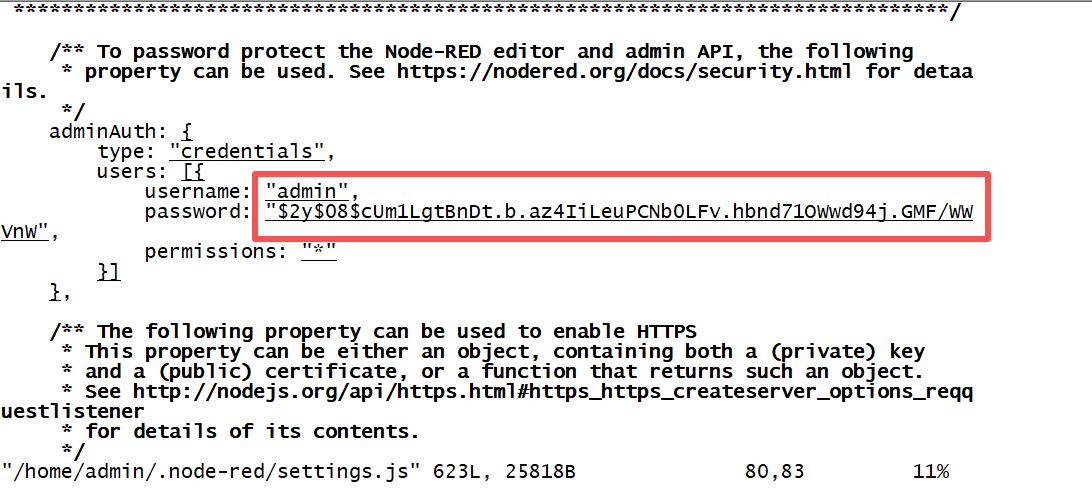
node-red admin hash-pwadmin@cp2b:~$ node-red admin hash-pw Password: $2y$08$cUm1LgtBnDt.b.az4IiLeuPCNb0LFv.hbnd71OWwd94j.GMF/WVnW-
Open the settings. js file, modify the content of adminAuth, and copy the string from earlier. Save and exit.
-
Restart Ubuntu
