CoolPi 4B硬件扩展四:GPIO
-
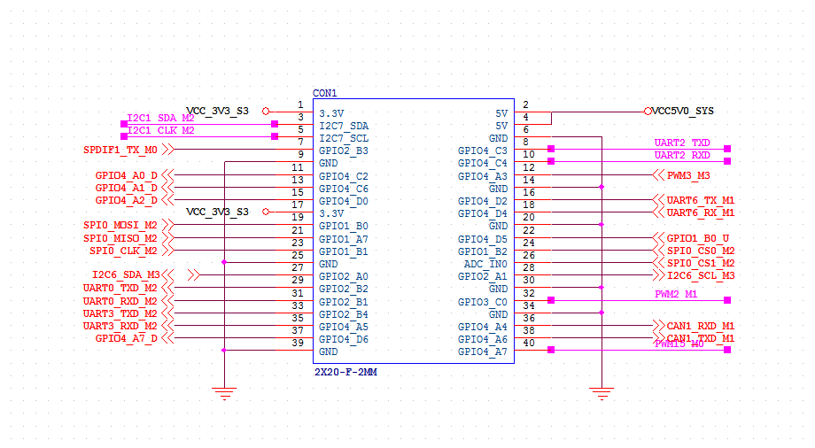
40PIN连接器除了debug串口和I2C6,其它都可以用作通用IO。所有的GPIO都支持中断、上下拉和驱动强度配置。
GPIO列表
PIN序号 GPIO编号 节点编号 默认状态 IO电平 3 GPIO0_D5 29 UP TTL 3.3V 5 GPIO0_D4 28 UP TTL 3.3V 7 GPIO1_B7 47 UP TTL 3.3V 11 GPIO4_A0 128 DOWN TTL 3.3V 13 GPIO4_A1 129 DOWN TTL 3.3V 15 GPIO4_A2 130 DOWN TTL 3.3V 19 GPIO1_B2 42 DOWN TTL 3.3V 21 GPIO1_B1 41 DOWN TTL 3.3V 23 GPIO1_B3 43 DOWN TTL 3.3V 29 GPIO4_A3 131 DOWN TTL 3.3V 31 GPIO4_A4 132 DOWN TTL 3.3V 33 GPIO4_A5 133 DOWN TTL 3.3V 35 GPIO4_A6 134 DOWN TTL 3.3V 37 GPIO4_A7 135 DOWN TTL 3.3V 12 GPIO1_A7 39 UP TTL 3.3V 16 GPIO1_A1 33 DOWN TTL 3.3V 18 GPIO1_A0 30 DOWN TTL 3.3V 22 GPIO1_B0 40 UP TTL 3.3V 24 GPIO1_B4 44 UP TTL 3.3V 26 GPIO1_B5 45 UP TTL 3.3V 32 GPIO3_B1 105 UP TTL 3.3V 36 GPIO4_B2 106 UP TTL 3.3V 38 GPIO4_B3 107 UP TTL 3.3V 40 GPIO3_C3 115 UP TTL 3.3V 测试命令
向内核申请GPIO,写入对应的GPIO值直接申请,比如申请控制GPIO4A0,则使用命令:
echo 128 > /sys/class/gpio/export写入后,可以看到已经生成节点:
/sys/class/gpio/gpio128/相应gpio节点下面的接口,比如GPIO4A0:
root@ubuntu:~# ll /sys/class/gpio/gpio128/
total 0
drwxr-xr-x 3 root root    0 Nov 21 15:23 ./
drwxr-xr-x 3 root root    0 Nov 21 15:23 ../
-rw-r--r-- 1 root root 4096 Nov 21 15:24 active_low
lrwxrwxrwx 1 root root    0 Nov 21 15:24 device -> ../../../gpiochip4/
-rw-r--r-- 1 root root 4096 Nov 21 15:24 direction
-rw-r--r-- 1 root root 4096 Nov 21 15:24 edge
drwxr-xr-x 2 root root    0 Nov 21 15:24 power/
lrwxrwxrwx 1 root root    0 Nov 21 15:24 subsystem -> ../../../../../../class/gpio/
-rw-r--r-- 1 root root 4096 Nov 21 15:23 uevent
-rw-r--r-- 1 root root 4096 Nov 21 15:24 value
设置GPIO4A0为输出口
root@ubuntu:/sys/class/gpio/gpio128# echo out >direction
root@ubuntu:/sys/class/gpio/gpio128# cat direction
out
设置输出高电平
root@ubuntu:/sys/class/gpio/gpio128# cat value
0
root@ubuntu:/sys/class/gpio/gpio128# echo 1 >value
root@ubuntu:/sys/class/gpio/gpio128# cat value
1
实际万用表测试PIN 11输出的电压为3.3V
备注:
-
direction: 参数为“out”(输出)和“in”(输入),可读可写;
-
value: 参数为“0”(低电平)和“1”(高电平),可读可写;
-
edge:可以监听对应引脚的事件,需要把direction设置为输入
参数为”none”(无中断触发), “rising”(上升沿触发), “falling”(下降沿触发), “both”(上升、下降都沿触发),用户层可以使用poll,设置events为POLLPRI | POLLERR等待事件触发,当对应的模式触发后,会返回事件的消息,此时需要读取value值,以表示改触发已经处理,否则会一直poll到原事件; -
active_low:此值可以反转value中的值;
-
-
 大 大法师 referenced this topic on
-
ugh per usual on this site none of these commands work :rolls eyes:
-
@zensation
Can you be more specific about which commands are not working. -
@george yes from the very start: echo 128 > /sys/class/gpio/export does not create a node
-
@george im trying to access the gpio because i have a custom hardware hat that needs gpio105 (pin 32) to be pulled down and i dont see any other way to pull down the input even though the documentation on the gpio page says that all IO can be set up with pull up or pull down resistors. pin 32 seems only to be pull up
-
@zensation
First, set the password for the root user, and then log in as root.coolpi@Ubuntu:~$ sudo passwd root [sudo] password for coolpi: New password: BAD PASSWORD: The password is shorter than 8 characters Retype new password: passwd: password updated successfully coolpi@Ubuntu:~$ su Password: root@Ubuntu:/home/coolpi# echo 128 > /sys/class/gpio/export root@Ubuntu:/home/coolpi# cd /sys/class/gpio/ root@Ubuntu:/sys/class/gpio# ls export gpiochip0 gpiochip32 gpiochip64 unexport gpio128 gpiochip128 gpiochip509 gpiochip96 root@Ubuntu:/sys/class/gpio# -
@george have logged into root but only see certain gpio as i still try to piece the missing parts together. How can I then change the pull up and pull down resistors for certain input pins?
-
@zensation
The current operation method does not support configuring the up and down status. If you need to modify the up and down status of GPIO, you can use DTS's PINCTRL to achieve it.lcd { lcdpwr_en: lcdpwr-en { rockchip,pins = <1 RK_PC4 RK_FUNC_GPIO &pcfg_pull_down>; }; bl_en: bl-en { rockchip,pins = <4 RK_PA3 RK_FUNC_GPIO &pcfg_pull_none>; }; }; -
@george ok George where can i find this file to modify?
-
@george and can i do the same thing with an overlay in the config.txt or something? if so how? thx
-
@zensation
Software modification pull-down:- specifies that the default pull-down of GPIO needs to be modified in the kernel DTS file, path:/arch/arm64/boot/dts/rockchip. After the modification is completed, compile and generate a DTB file, and then replace it.
Hardware modification pull-down:
- You can change the default pull-down situation of IO by connecting a pull-down resistor to GPIO. The default pull-up change is to connect a 2K resistor to the GND network, and the default pull-down change is to connect a 4.7K resistor to a 3.3V power supply.
-
@george thanks for the info george...i tried adding a 2k resistor to ground on pin 32 to change it to change it from pull up to pull down as you mentioned, however that does not work and the pin voltage on 32 reads 1.034 volts. ill try other values of resistors and report which one works.
-
@zensation
If you need to use PWM function, it is recommended to use PIN12 (PWM3-M3). This port defaults to the pull-up port, and you can increase the resistance to ground by 2K. The default level can be reduced to below 0.6V. If you need GPIO function, except for PIN3 PIN5 PIN32 PIN40 PIN8 PIN10, all other IOs can use pull-down resistors to change the default level.
-
@george ok this explains things better. I have a HAT that was designed for the raspberry pi 4 and it has a power detection pin on pin 32. it needs to be pulled down in order to function because the hat sends 3.3v to the pin as long as incoming power is detected on the power in lines of the HAT. then when the incoming power dissapears from the hat incoming lines, pin 32 will be pulled low by the pull down resistor and the pi can execute some code. If i can figue out how to edit the dts file and recompile to dtb to change pin 32 to an internal pull down resistor i will do it that way. otherwise i guess i am stuck.
-
@george so here is where I am at. Ive spent a lot of time trying to figure this out but nothing is making sense so maybe you can give me a direct file of what will work. I have done this:
- navigate to folder of rk3588s-cp4.dtb (/boot/firmware/rk3588s-cp4.dtb)
- converted the dtb file to dts file using command: sudo dtc -I dtb -O dts rk3588s-cp4.dtb -o rk3588s-cp4.dts
- nano to open the file: sudo nano rk3588s-cp4.dts
heres where im stuck...theres nothing in that file that resembles the syntax you have sent me. I will attach the dts file in txt format here. can you edit it with the correction to change pin 32 from pull up to pull down? thanks!
rk3588s-cp4.txtalternatively, on line 1562 i find there is an entry for wake from suspend such as below.
rockchip,wakeup-config = <0x100>;
can you tell me how to change this line to enable GPIO wake from suspend? then I can use whatever GPIO I wish to wake the cool-pi 4b up when suspended without physically pushing the button. I have tried the syntax below but i get a syntax error when i try to convert it back to dtb file:
rockchip,wakeup-config = <
(0
| RKPM_GPIO_WKUP_EN
)
>; -
after doing more research it seems you have to compile the dts files into a pre processed file with cpp command before you can compile into a dtb file with the dtc command. so i got that figured out and can change the io pullups.
however im still struggling with the wakeup from suspend conditions. I enabled several of them but none seem to work. usb hubs are suspended so usb wakeup doesnt work, the Uart0 wakeup condition is enabled but doesnt wakeup the processor either. ill have to keep digging, but if you are anyone knows how to wakeup from a source other than the power button that would be great to know. as it stands ill have to add a secondary microprocessor to the system to ground the power button contact physically to wake up the board.
-
您好,我想用C++代码实现对sys/class/gpio的操作,这意味着我不能使用带sudo的命令,但是它提示我Permission denied,即使我解除了写入export的限制,但value和direction依然没有权限写入,在网上搜寻了很多方法无果,请问有好的建议吗
-
-
This post is deleted!