How to drive a TTL (RGB) interface LCD
-
Cool Pi does not have a TTL interface. If you want to drive a TTL interface screen, you need to use a bridge chip. At present, the MIPI to TTL interface chip supports ICN6211 by default. The following details how to use ICN6211 to drive a TTL interface LCD module.
-
Specification
ICN6211_mipi2rgb.brd
MIPI_RGB_162.DSN
ICN6211_MIPI_RGB_specification_V04.pdf -
Block diagram

-
DTS configuration
Enable the following nodes,mipi_dcphy0 dsi0 dsi0_in_vp3 backlight pwm13 .
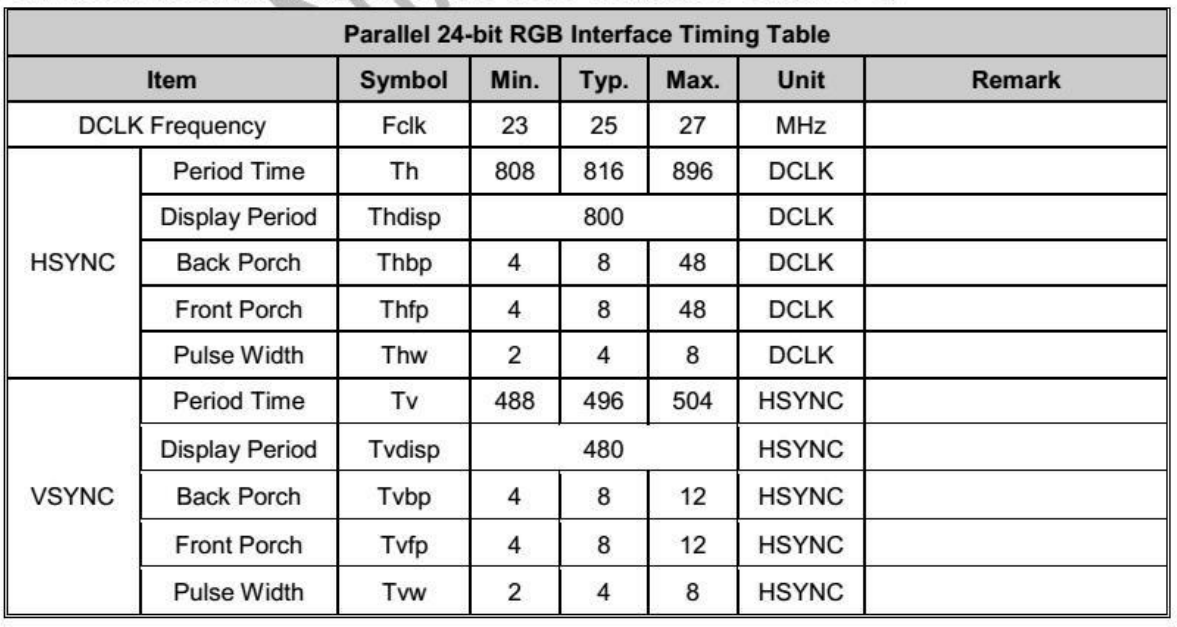
&mipi_dcphy0 { status = "okay"; }; &dsi0 { status = "okay"; dsi0_panel: panel@0 { status = "okay"; compatible = "simple-panel-dsi"; reg = <0>; backlight = <&backlight>; reset-delay-ms = <60>; enable-delay-ms = <60>; prepare-delay-ms = <60>; unprepare-delay-ms = <60>; disable-delay-ms = <60>; dsi,flags = <(MIPI_DSI_MODE_VIDEO | MIPI_DSI_MODE_VIDEO_BURST | MIPI_DSI_MODE_LPM | MIPI_DSI_MODE_EOT_PACKET)>; dsi,format = <MIPI_DSI_FMT_RGB888>; dsi,lanes = <2>; panel-init-sequence = [ 23 00 02 7A C1 23 00 02 20 20 23 00 02 21 E0 23 00 02 22 13 23 00 02 23 08 23 00 02 24 04 23 00 02 25 08 23 00 02 26 00 23 00 02 27 08 23 00 02 28 04 23 00 02 29 08 23 00 02 34 80 23 00 02 86 29 23 00 02 B5 A0 23 00 02 5C FF 23 00 02 2A 01 23 00 02 56 92 23 00 02 6B 71 23 00 02 69 15 23 00 02 10 40 23 00 02 11 88 23 00 02 B6 20 23 00 02 51 20 23 00 02 09 10 05 78 01 11 05 1E 01 29 ]; panel-exit-sequence = [ 05 00 01 28 05 00 01 10 ]; disp_timings0: display-timings { native-mode = <&dsi0_timing0>; dsi0_timing0: timing0 { clock-frequency = <25000000>; hactive = <800>; vactive = <480>; hfront-porch = <8>; hsync-len = <4>; hback-porch = <8>; vfront-porch = <8>; vsync-len = <4>; vback-porch = <8>; hsync-active = <0>; vsync-active = <0>; de-active = <0>; pixelclk-active = <0>; }; }; ports { #address-cells = <1>; #size-cells = <0>; port@0 { reg = <0>; panel_in_dsi: endpoint { remote-endpoint = <&dsi_out_panel>; }; }; }; }; ports { #address-cells = <1>; #size-cells = <0>; port@1 { reg = <1>; dsi_out_panel: endpoint { remote-endpoint = <&panel_in_dsi>; }; }; }; }; &dsi0_in_vp3 { status = "okay"; }; &backlight { pwms = <&pwm13 0 25000 0>; status = "okay"; }; &pwm13 { status = "okay"; pinctrl-names = "active"; pinctrl-0 = <&pwm13m2_pins>; };- Configure lcdc parameters according to LCD specifications.
LCD specification 5inch DSI LCD (B).pdf

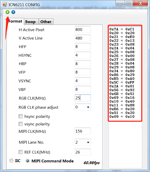
disp_timings0: display-timings { native-mode = <&dsi0_timing0>; dsi0_timing0: timing0 { clock-frequency = <25000000>; hactive = <800>; vactive = <480>; hfront-porch = <8>; hsync-len = <4>; hback-porch = <8>; vfront-porch = <8>; vsync-len = <4>; vback-porch = <8>; hsync-active = <0>; vsync-active = <0>; de-active = <0>; pixelclk-active = <0>; }; };- Generate the initialization sequence of ICN6211 according to the LCD specification.
ICN6211 initialization tool ICN6211 Config.rar

Copy the initialization sequence to DTS according to the command format of rockchip.
Command format description:
23 00 02 7A C1
[Command word] [Delay] [Packet length] [Register] [Value]
Note that the last 11 29 command is reserved. This is the DSI standard command to open the display.panel-init-sequence = [ 23 00 02 7A C1 23 00 02 20 20 23 00 02 21 E0 23 00 02 22 13 23 00 02 23 08 23 00 02 24 04 23 00 02 25 08 23 00 02 26 00 23 00 02 27 08 23 00 02 28 04 23 00 02 29 08 23 00 02 34 80 23 00 02 86 29 23 00 02 B5 A0 23 00 02 5C FF 23 00 02 2A 01 23 00 02 56 92 23 00 02 6B 71 23 00 02 69 15 23 00 02 10 40 23 00 02 11 88 23 00 02 B6 20 23 00 02 51 20 23 00 02 09 10 05 78 01 11 05 1E 01 29 ];- The TTL signal can be output normally by recompiling and replacing the kernel.

-
-
@george how?
-
@retroman Has been updated, please check.