Coolpi CM5-Laptop 5G module design
-
Module selection
-
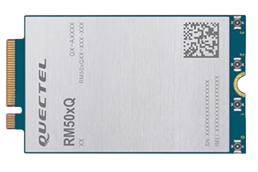
RM500Q-GL is a 5G NR/LTE-A/UMTS/HSPA+ wireless communication module with receive diversity. It
provides data connectivity on 5G NR SA and NSA, LTE-FDD, LTE-TDD, DC-HSDPA, HSPA+, HSDPA,
HSUPA and WCDMA networks with standard PCI Express M.2 interface.It supports embedded operating systems such as Windows, Linux and Android, and also provides GNSS
and voice functionality to meet specific application demands. -
The following table shows the frequency bands and GNSS type of RM500Q-GL module.
Mode RM500Q-GL 5G NR n1/n2/n3/n5/n7/n8/n12/n20/n25/n28/n38/n40/n41/n48/n66/n71/n77/n78/n79 LTE-FDD B1/B2/B3/B4/B5/B7/B8/B9/B12/B13/B14/B17/B18/B19/B20/B25/B26/B28/B29/B30/B32/B66/B71 LTE-TDD B34/B38/B39/B40/B41/B42/B43/B46/B48 WCDMA B1/B2/B3/B4/B5/B8/B19 GNSS GPS/GLONASS/BeiDou/Galileo
Schematic design
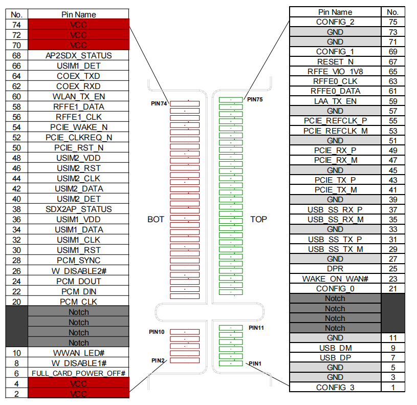
Module Pin Definition
- Module pin layout,It can support PCIE interface or USB3.0 interface. We chose USB3.0 interface design, which is relatively easy to handle for compatibility and driver.
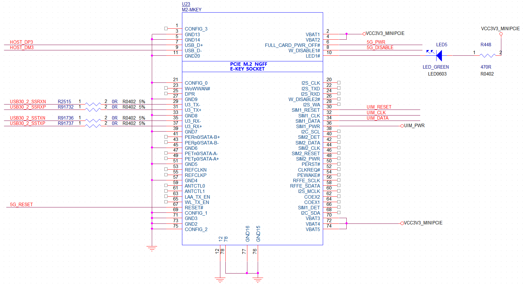
Signal connection
-
Schematic encapsulation definition, based on the PIN definition of the module.When connecting USB3.0 or PCIE signals, they should be crossed, with TX connected to processor RX and RX connected to processor TX.
-
Select the minimum GPIO method because the Coolpi CM5 laptop completely loses power during sleep, so it does not support module wake-up system. The GPIO connection is as follows:
-
The following table describes the signal list, which is mainly divided into power supply, USB3.0, SIM card, and control signal.
Pin No Pin Name I/O Power Domain Description 2, 4, 70, 72, 74 VCC PI 3.135-4.4 V 3.7 V typical DC supply 3, 5, 11, 27, 33, 39, 45, 51, 57, 71, 73 GND Ground 7 USB_DP AI/AO USB 2.0 differential data bus (+) Require differential impedance of 90 Ω 9 USB_DM AI/AO USB 2.0 differential data bus (-) Require differential impedance of 90 Ω 29 USB_SS_TX_M AO USB 3.1 transmit data (-) Require differential impedance of 90 Ω 31 USB_SS_TX_P AO USB 3.1 transmit data (+) Require differential impedance of 90 Ω 35 USB_SS_RX_M AI USB 3.1 receive data (-) Require differential impedance of 90 Ω 37 USB_SS_RX_P AI USB 3.1 receive data (+) Require differential impedance of 90 Ω 36 USIM1_VDD PO Power supply for (U)SIM1 card Class B (3.0 V) 34 USIM1_DATA IO (U)SIM1 card data 1.8/3.0 V power domain 32 USIM1_CLK DO (U)SIM1 card clock 1.8/3.0 V power domain 30 USIM1_RST DO (U)SIM1 card reset 1.8/3.0 V power domain 66 USIM1_DET DI (U)SIM1 card insertion detection Internally pulled 6 FULL_CARD_POWER_OFF# DI Turn on/off of the module. When it is at low level, the module is turned off. When it is at high level, the module is turned on. Internally pulled down with a 100k Ω resistor 67 RESET# DI Reset the module.Active LOW. Internally pulled up to 1.8 V with a 100k Ω resistor 8 W_DISABLE1# DI Airplane mode control.Active LOW. 1.8/3.3 V power domain 10 LED_1# WWAN_LED# OD RF status indication LED It is an open drain and active LOW signal. Power supply
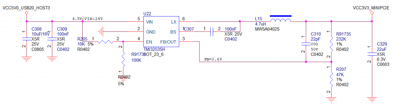
The following figure shows a reference design for +5 V input power source based on an DC-DC
TMI3253SH. The typical output of the power supply is about 3.7 V and the maximum load current is 3A.
Power sequence
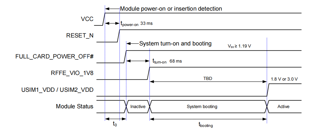
The turn-on scenario is illustrated in the following figure.
- tpower-on is time the interval between VCC and RESET_N HIGH level, which is a typically 33 ms. It is
measured when RESET_N is not pulled down by the host device. - tturn-on is the time interval between FULL_CARD_POWER_OFF# HIGH level and RFFE_VIO_1V8(an internal LDO output) HIGH level, which is typically 68 ms.
- tbooting is the time interval between RFFE_VIO_1V8 HIGH level and the USIM_VDD power-on.
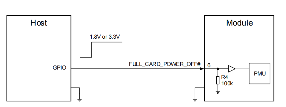
Turn on the Module
It is recommended to use a host GPIO to control FULL_CARD_POWER_OFF#. A simple reference circuit
is illustrated in the following figure.
Turn off the Module
Pulling down the FULL_CARD_POWER_OFF# pin will turn off the module. The turn off
scenario is illustrated in the following figure.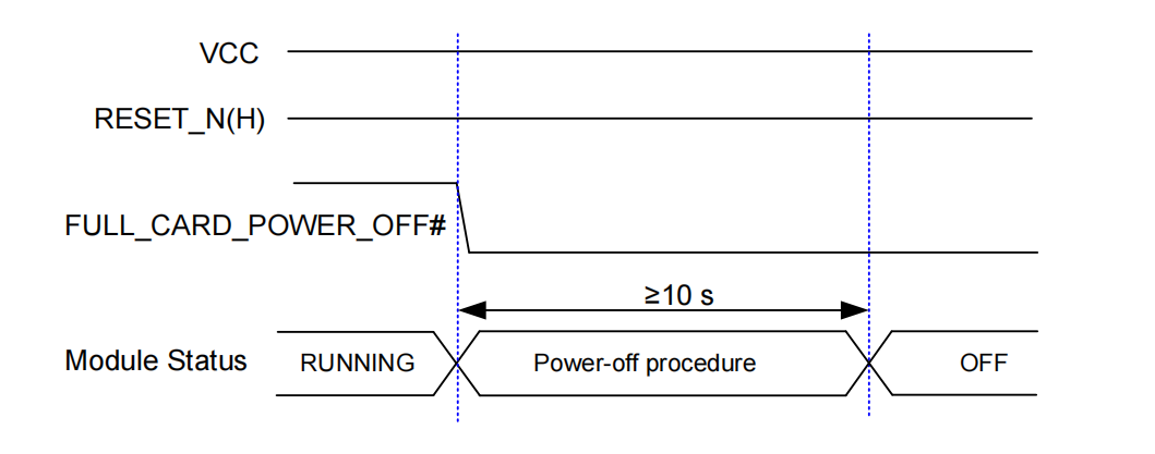
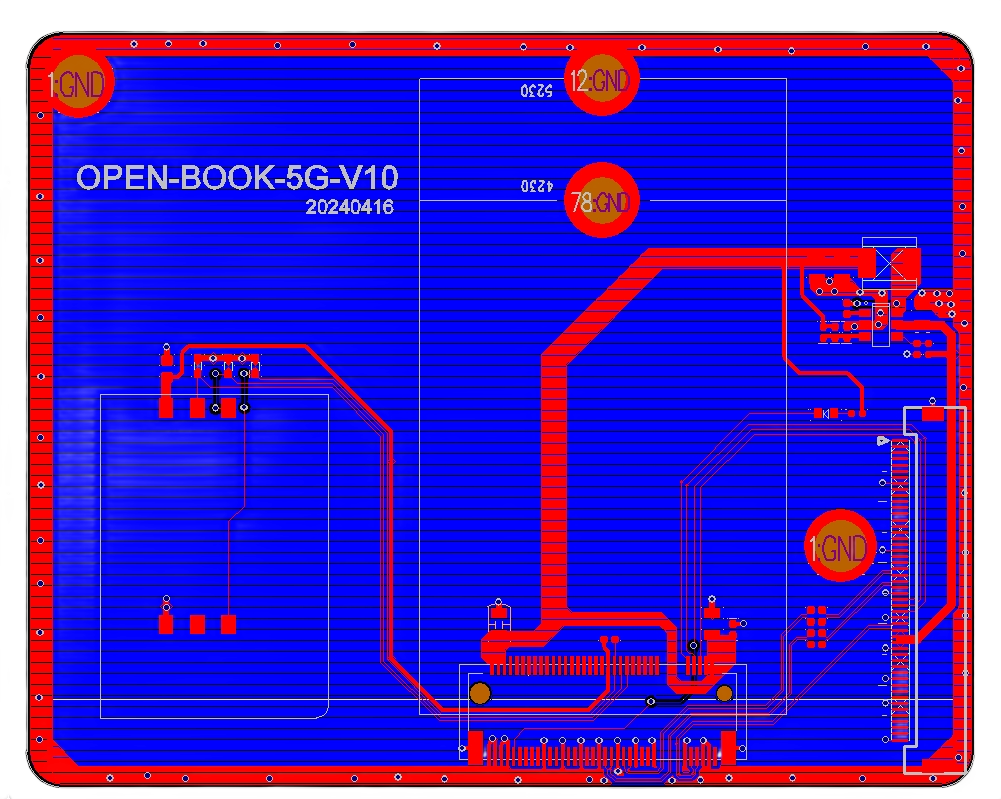
PCB design
- Layout diagram
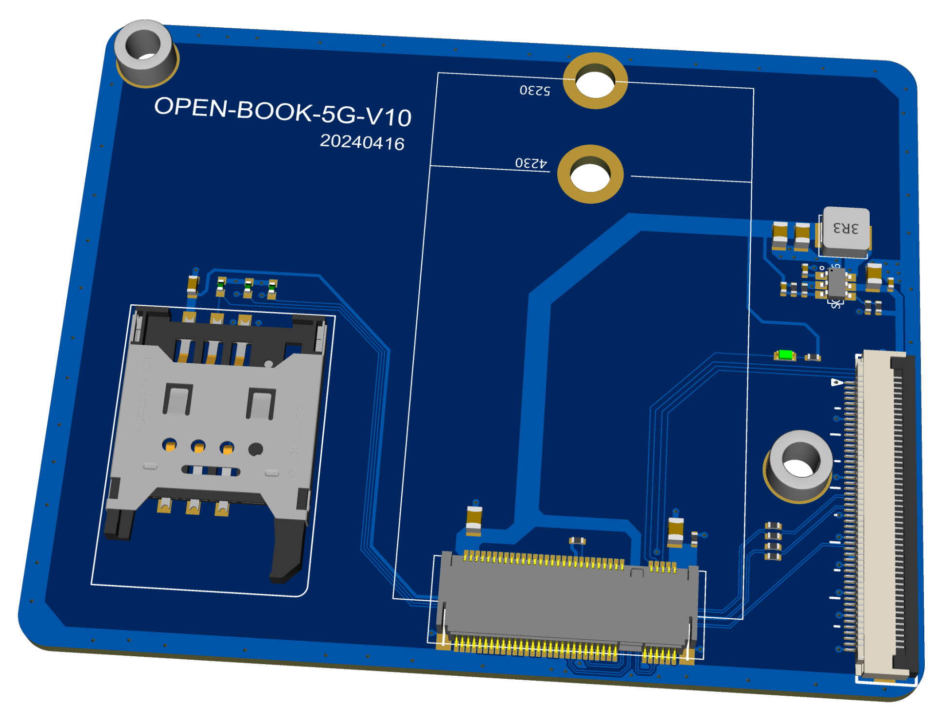
- 3D simulation diagram
Welding and hardware debugging
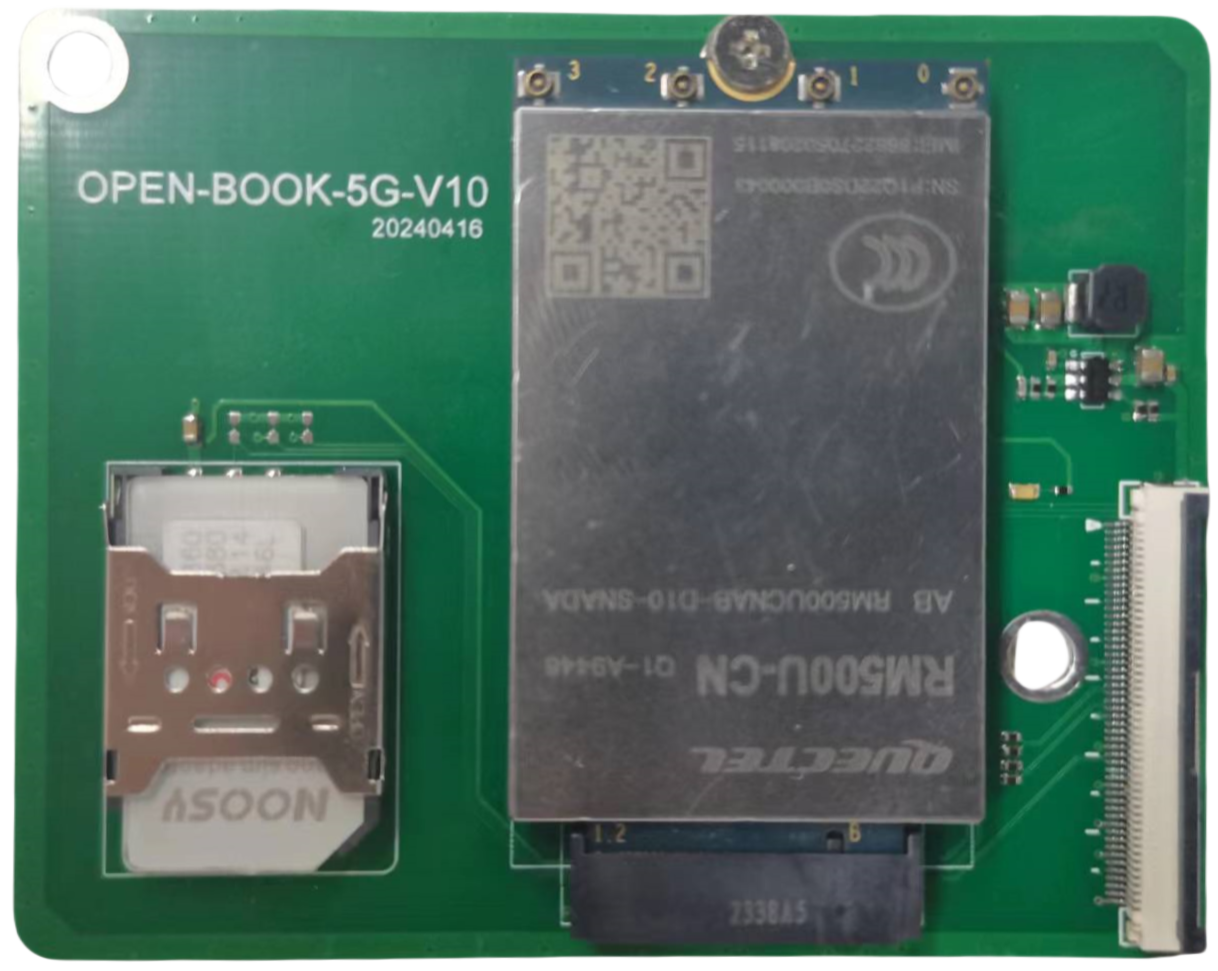
-
-
@george
我用的是RM500U-CN的 现在CM5有集成5G模组卖的吗?
我用USB3.0接的模组 编译了内核 可以用 但是这个内核如果接USB无线网卡 内核就会崩溃
内核是按照5G模组的文档来改的 -
@jugg
这个要看具体的log信息,是驱动有冲突还是什么问题,你可以使用PCIE的网卡暂时规避这种问题,CM5的机器可以支持多种型号的PCIE+USB网卡。
这个模组目前是针对CM5的笔记本设计的,CM5-EVB暂时用不了。 -
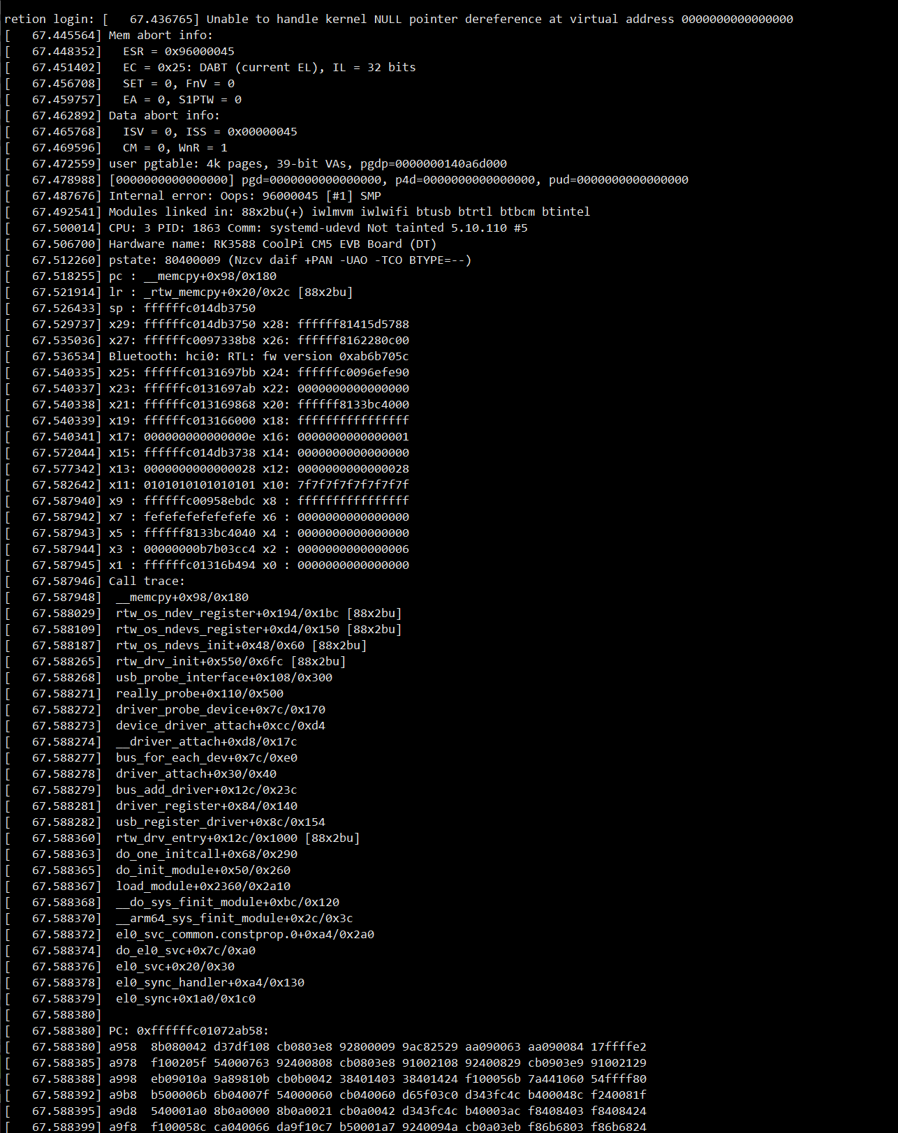
这个就是当时的log
这一块内核崩了 系统还可以正常运行
用的是CM5支持的无线网卡 -
@jugg
这个是RTL的驱动注册有问题,你可以加LOG信息在rtk的驱动里边跟踪一下,定位到具体哪里报异常。然后再想办法解决。 -
@george
你们的nootbook加了5G模组 再接USB网卡有没有这个问题 -
@jugg
这个5G模组还在设计中。 -
Software debugging
- Can recognize the network card normally
FM160-NA
[  209.139782] usb 6-1: new SuperSpeed Gen 1 USB device number 3 using xhci-hcd
[  209.158752] usb 6-1: LPM exit latency is zeroed, disabling LPM.
[  209.159341] usb 6-1: New USB device found, idVendor=2cb7, idProduct=0104, bcdDevice= 5.04
[  209.159345] usb 6-1: New USB device strings: Mfr=1, Product=2, SerialNumber=3
[  209.159348] usb 6-1: Product: Fibocom FM160 Modem_SN:A5206AEB
[  209.159351] usb 6-1: Manufacturer: Fibocom
[  209.159354] usb 6-1: SerialNumber: a5206aeb
[  209.334460] usb 6-1: GSM modem (1-port) converter now attached to ttyUSB0
[  209.334960] usb 6-1: GSM modem (1-port) converter now attached to ttyUSB1
[  209.335465] usb 6-1: GSM modem (1-port) converter now attached to ttyUSB2
[  209.335869] usb 6-1: GSM modem (1-port) converter now attached to ttyUSB3
[  209.369699] qmi_wwan 6-1:1.4 wwan0: register 'qmi_wwan' at usb-xhci-hcd.4.auto-1, WWAN/QMI device, 0e:2e:b9:55:d8:4f
RM500U-CN
[ 1060.540438] usb 6-1: new SuperSpeed Gen 1 USB device number 4 using xhci-hcd [ 1060.558057] usb 6-1: New USB device found, idVendor=2c7c, idProduct=0900, bcdDevice= 4.04 [ 1060.558062] usb 6-1: New USB device strings: Mfr=1, Product=2, SerialNumber=3 [ 1060.558065] usb 6-1: Product: RM500U-CN [ 1060.558068] usb 6-1: Manufacturer: Quectel [ 1060.558071] usb 6-1: SerialNumber: 0123456789ABCDEF [ 1060.614822] cdc_ether 6-1:1.0 usb0: register 'cdc_ether' at usb-xhci-hcd.4.auto-1, CDC Ethernet Device, 4a:b9:e7:e7:04:47 -
hello 这个模组现在可用了吗,在售卖了吗请问
-
@Hyperkiller
这个模组下周在店铺上链接。 -